Data transmission over sound is used in many communication protocols, the most common being Dual-Tone Multi-Frequency signaling (DTMF). It is used to dial phone numbers and the frequency combinations chosen for the digits are very familiar to the general public. It was also used in early modems to request internet connections and its characteristic sound is nostalgic for many people.
However, to push the data rate to higher values, ultrasound (sound waves of frequency higher than 20 kHz), is a better choice than audible sound given that it is relatively unaffected by noise produced by human speech and, at the same time, does not disturb the user.
Nowadays, some cellphone and computer applications use ultrasound to transmit data. However the channel’s characteristics, such as echo, high noise for audible range and inadequate hardware for ultrasonic range, are very difficult to handle and severely limit the data rate. Applications that use it to transmit data are usually academic. Distance and speed measurement and sonar devices are where ultrasound is most useful.
The device described on this report consists of a pair of microcontrollers assisted by analog circuitry, which transmit data to each other through sound.
When a key is pressed on the keyboard connected to the transmitter microcontroller, a corresponding sound wave is generated by the speaker. The microphone converts the sound wave to an analog electric signal, which is converted to a digital signal and interpreted by the receiver. The data is then shown on an LCD display.
The initial design would use ultrasound to transmit the information as to not disturb the user and the data would be converted back into the PS2 keyboard protocol in order the mimic the keyboard itself. That way, a computer would experience no difference between a signal received from the device and a signal from an actual keyboard. Due to unforeseen challenges, we opted for a less sophisticated design, which uses audible sound.
The idea for this project came from a lab in ECE 4760, the microcontroller design class, involving DTMF. We noticed that sound was an interesting way to transmit information and decided to create a transmitter receiver pair using this method.
High Level Design
Logical Structure
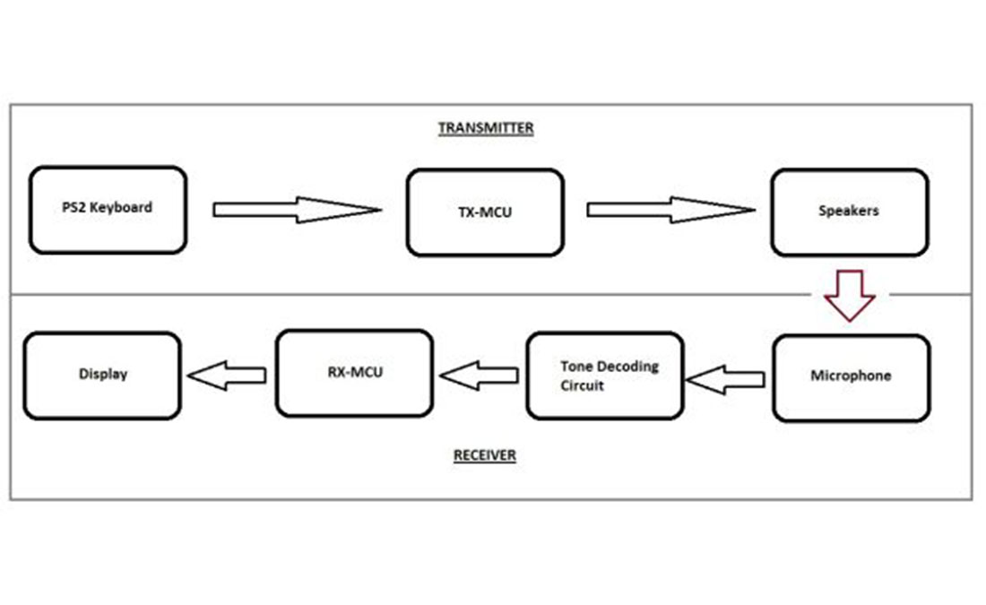
At a high level, our system consists of two main components: a transmitter unit, and a receiver unit.
The transmitter consists of a keyboard, a microcontroller (TX-MCU), and a set of speakers. Whenever a key on the keyboard is pressed, the keyboard drives two signals, CLK and DATA. The TX-MCU samples DATA on the falling edge of CLK to build a data packet representing the key that was pressed, then transmits the packet as a combination of two alternating on/off tones (one at 8 kHz, another at 5 kHz) over the speakers, where one tone represents CLK and the other represents DATA.
It is important to note that the keyboard CLK is driven at a very high speed (roughly 13 kHz). At these speeds it is impossible to represent the signal as on/off 8 kHz or 5 kHz tones, as even a single period would not fit within the clock pulse, let alone the number of periods per pulse necessary to be recognized by the receiver. As a result, a significantly slower transmission rate must be used by the TX-MCU.
The tones output by the speakers are then picked up with a microphone, and the resulting analog electric signal passes through three stages of high pass filters and two amplifiers before being input into a tone-decoding circuit. As it’s name suggests, the tone-decoding circuit consists of two tone decoders that are tuned to detect the presence of 8 kHz and 5 kHz frequency signals, each driving a low output if such frequencies are detected. In this way digital CLK and DATA signals can be reconstructed. However, these signals tend to oscillate slightly when transitioning between low and high, which is undesirable. To counter this, the signal is low-pass filtered and passed through a comparator with hysteresis. The resulting signals are finally then considered suitable for the receiver microcontroller (RX-MCU) to use as inputs. Once again, the RX-MCU samples DATA on the falling edge of CLK to build a data packet representing the key that was pressed. From this, the RX-MCU is able to determine the corresponding character and ouput it to the LCD.
The user interacts with the overall system using the keyboard. Assuming there are no errors in transmission, valid key-presses on the keyboard will result in the corresponding character being output to the LCD after the previously output character, as in a typical text editor. Going past the end of either of the two LCD lines will result in the text wrapping around to the beginning of the other line. Aside from the typical alphanumeric keys, there are additional keys with functions associated with them.
| Key | Result |
|---|---|
| <Shift> | Output alternate character |
| <Backspace> | Erase last character, move cursor back by one |
| <Enter> | Clear current line, move cursor to beginning of current line |
| <Esc> | Clear both lines, move cursor to beginning of first line |
Design Decisions
Tone Generation
We considered several different options for generating tones at a target frequency.
One of the first methods that came to mind was using Direct Digital Synthesis (DDS) as in Lab 2 of this class. Obvious benefits to this approach were the ease and familiarity that came with having implmented this approach previously. One huge restriction at the time was the fact that DDS was limited by the microcontroller to a maximum frequency of roughly 8 kHz, but, with some handling, we decided that the harmonics could be used
We also considered using a pure hardware implementation, such as using a 555 timer or phase-shift oscillators.
Lastly, we considered low-passing a square wave, which could be generated either by the MCU or the LM 567 IC.
Even though it is not the most appropriate option, this design uses DDS. We had unexpected difficulties implementing some of the other options and opted for DDS, as we were more familiar and experienced with it.
Tone Detection
As before, we considered several different options for detecting tones at a target frequency.
One approach was to use a combination of an Analog-to-Digital Converter (ADC) and Goertzel’s algorithm, which is a procedure with detects the frequency component of a single tone in a signal, primarily used in embedded systems. In case the frequency of the signal was too high for the internal ADC, an external one could be used or the frequency could be brought down by multiplying it by a sine wave with a frequency a little lower than the carrier with the IC AD633.
Another approach was to use the LM567 tone decoders, which involved a relatively simple hardware implementation, and was capable of detecting up to 500 kHz.
Our first attempt was using band-pass filters and rectifying the signal, but low order analog filters proved insufficient for this application. Then, we decided to use LM567’s.
Hardware
Hardware Overview
Our system consists of two main physical components: a transmitter circuit, and a receiver circuit. The transmitter circuit is relatively simple, consisting only of a microcontroller, a keyboard, a low-pass filter to filter the output of the PWM, and a set of speakers to output the corresponding tones. The receiver circuit is significantly more complex, and can be subdivided into a microcontroller, a microphone circuit to pick up, filter, and amplify the tones, a tone-decoding circuit to detect the presence of certain frequencies in a signal, and a low-pass hysterisis circuit to clean up the resulting digital signal.
Hardware Design: Transmitter
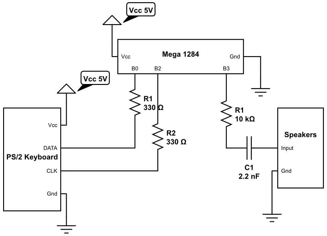
As mentioned previously, the transmitter circuit is relatively straightforward, as most of the work is done in software. A schematic for the overall circuit can be found in the appendix. PIN B0 and PIN B2 of the TX microcontroller are connected to the PS/2 keyboard DATA and CLK lines respectively, with 330Ω resistors in between for protections purposes. The output of the PWM at PORT B3 is passed through a low-pass filter to drive a set of speakers, which has its own power supply. For the low pass filter, we needed a resistor that was high enough so as not to load the port pin, yet low enough to be below the speaker input resistance of 30kΩ. We ultimately settled on a 10kΩ resistor. We then chose a capacitance of 2.2nF for a cut-off frequency of ~7.25 kHz. Though this is technically below 8 kHz, we were still able to reliably detect 8kHz tones.
Hardware Design: Receiver
The receiver circuit is where most of the complexity lies, and can be subdivided into microphone, tone decoder, and hysteresis sub-circuits, which we will examine in more depth in the following sections. A schematic for the combined receiver circuit can be found in the appendix.
Microphone Sub-Circuit
The microphone stage is shown above. This is a modified version of the design presented in class to adapt the signal for Analog-to-Digital Conversion.
The microphone is set into a voltage divider with a 10kΩ resistor. This value provides the best results since it sets the DC voltage on the microphone to a value close to half of Vcc, therefore the ratio between the AC voltage and changes of the resistance of the microphone is maximum.
C1 isolates the DC voltage between the microphone and the second voltage divider R2 and R3, which are set so that the voltage at the input of the amplifier is half of Vcc. This guarantees the input for the amplifier will not be a negative voltage, which cannot be handled with the power sources available. The two amplifiers are set to gains of 50 and 10, respectively. C2 and C3 cut off the DC current of the amplifiers, effectively turning them into buffers for DC voltages. The amplifiers are implemented using LF353 for its fairly high bandwidth-gain property.
Note this circuit has 3 high-pass filters: C1 and R2||R3, C2 and R5, and C3 and R7. Their values are set to cut-off frequencies of approximately 14, 7 and 14 kHz, respectively, to remove noise from human speech. Ideally, these values should have been adjusted to lower cut-off frequencies since the final design used 5 kHz and 8 kHz, but this could not be done due to time constraints.
Tone Decoder Sub-Circuit
The tone decoder stage is shown above. The input is pin 3 and the output is pin 8.
There are two of these blocks, one for each frequency used. They are implemented by the LM567CN. The configuration used is the one described on the data sheet. Rf, Cf and the center frequency of the tone decoder are related by the following equation:
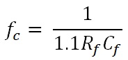
On this design, capacitors of 10nF and 5kΩ potentiometers were used to set the center frequency.
One of the problems encountered was that since C1 and C2 are electrolytic and maintain their charges for a long time, Rf had to be adjusted after every power cycle to achieve the proper center frequency.
Another problem encountered was that when transitioning between high and low states the tone decoder output would occasionally oscillate. This proved to be particularly troublesome as the resulting falling edges would trick the receiver microntroller into thinking that a new data bit had arrived.
Parts List:
| Part | Vendor | Unit Cost | Quantity | Total Cost |
|---|---|---|---|---|
| ATmega1284P | Lab Stock | $5.00 | 2 | $10.00 |
| White Board | Lab Stock | $6.00 | 3 | $18.00 |
| PS/2 Keyboard | Lab Stock | $0.00 | 1 | $0.00 |
| Logitech S-120 PC Multimedia Speakers | Lab Stock | $0.00 | 1 | $0.00 |
| Electret Microphone | Lab Stock | $1.00 | 1 | $1.00 |
| LCD (16×2) | Lab Stock | $8.00 | 1 | $8.00 |
| LM567 Tone Decoder | DigiKey | $1.50 | 2 | $3.00 |
| LF353 Op Amp | Lab Stock | $0.00 | 2 | $0.00 |
| LM358 Op Amp | Lab Stock | $0.00 | 1 | $0.00 |
| Potentiometer | Lab Stock | $0.00 | 4 | $0.00 |
| Wires, Resistors and Capacitors | Lab Stock | $0.00 | Several | $0.00 |
| Total | $40.00 |
For more detail: Acoustic Modem Using Atmega1284