Summary of Arduino Without External Clock Crystal on ATmega328
This article details how to build a minimal Arduino UNO on a breadboard using an ATmega328p microcontroller with its internal 8 MHz oscillator, eliminating the need for external crystals and capacitors. It covers installing hardware support in the IDE, burning bootloaders using either another Arduino or an FTDI adapter, and programming the chip. The guide emphasizes low-power applications suitable for intermittent tasks like irrigation or solar tracking.
Parts used in the Minimal Arduino UNO:
- ATmega328p microcontroller
- Breadboard
- Arduino board (used as programmer)
- FTDI USB to Serial Adapter (FT232RL breakout board)
- Male headers (for soldering to FTDI board)
- Battery (for power supply)
- USB cable (Mini type-B)
Story
Making a Minimal Arduino UNO on a Breadboard
Most people are successful in making Arduino with minimal circuitry, but use the 16 MHz crystal. We can remove that, too, along with 22 pF capacitors. You can configure the ATmega328 to use its internal 8 MHz RC oscillator as a clock source.
Install Support for Hardware Configuration
- Download this hardware configuration archive: breadboard-1-6-x.zip, Breadboard1-5-x.zip or Breadboard1-0-x.zip depending on which IDE you use.
- Create a “hardware” sub-folder in your Arduino sketchbook folder (whose location you can find in the Arduino preferences dialog). If you’ve previously installed support for additional hardware configuration, you may already have a “hardware” folder in your sketchbook.
- Move the breadboard folder from the zip archive to the “hardware” folder of your Arduino sketchbook.
- Restart the Arduino software.
- You should see “ATmega328 on a breadboard (8 MHz internal clock)” in the Tools > Board menu.
Once you’ve done this, you can burn the bootloader and upload programs onto your ATmega328.
Putting Stuff on Breadboard

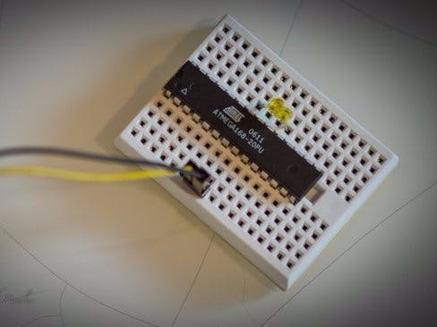
Get all the stuff listed above. Moreover, keep a pin mapping of the ATmega328P handy while making the circuit.
Using ATmega Without UNO Bootloader
First of all, we need to burn the bootloader to the ATmega chip if you bought a blank microcontroller having no bootloader, so that it can be a programmable entity.
- Refer to the schematics and place the ATmega chip in the breadboard.
- Open the ArduinoISP firmware (in Examples) to your Arduino board.
- Select the items in the Tools > Board and Serial Port menus that correspond to the board you are using as the programmer (not the board being programmed).
- Upload the ArduinoISP sketch.
- Select the item in the Tools > Board menu and be sure to select “ATmega328 on a breadboard (8MHz internal clock)” when burning the bootloader.
- Select the Arduino as ISP in the Tools > Programmer menu.
- Use the Burn Boot-loader command in the Tools menu.
Skip step 2 if you have done step 1.
2. Using ATmega with UNO boot-loader
If the ATmega is already boot-loaded, then just put it in the breadboard and we can proceed programming the ATmega328p microcontroller.
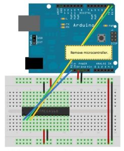
3. Programming the ATmega chip (using other Arduino)
- Remove the microcontroller of the Arduino you are using as the programmer.
- Refer to the schematics and pin mapping and connect the Rx and Tx of programmer Arduino to Tx and Rx of the breadboard Arduino respectively.
- Connect RESET of programmer Arduino to RESET of breadboard Arduino.
- Connect GND and VCC of breadboard Arduino to GND and VCC on programmer Arduino.
- Select the item in the Tools > Board menu and be sure to select “ATmega328 on a breadboard (8MHz internal clock)“.
- Check the port and click on “upload”.
Plug out the connections and now you can power it with a battery for months depending on the kind of project.
4. Programming the ATmega chip (using FTDI USB to Serial Adapter)
Curious what all the pin outs are for on the FT232RL breakout board? Simply flip it over! In this situation I’ll be using VCC (to supply 5V from the USB port to your board), GND, TXD, and RXD. [Refer to schematics]
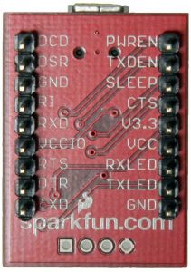
- This board comes without the headers when bought from market. So, solder the male header and plug it in the breadboard.
- Connect Rx of ATmega chip to Tx of board and Tx of ATmega chip to Rx of the board.
- Connect Vcc and GND to the power rails on the breadboard.
- Plug the USB mini type – B and connect it with your computer and upload the sketch using the Arduino IDE but always remember to select “ATmega328 on a breadboard (8MHz internal clock)“. It will take power from the USB but after disconnecting the USB, you can plug the battery terminals to the power rails of breadboard.
And the Arduino is ready.
Disclaimer: I would recommend you to make Arduino with internal 8 MHz clock only if your project doesn’t require many command lines to be executed in a very small interval of time. You can use them for projects which are small amount of work after some time and repeated, like water irrigation, solar tracker, etc.
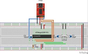
Schematics
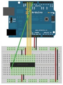
Uploading sketches to an ATmega on a breadboard(using another Arduino).
Uploading sketches to an ATmega on a breadboard(using FTDI 232RL Driver)
Code
// ArduinoISP
// Copyright (c) 2008-2011 Randall Bohn
// If you require a license, see
//     http://www.opensource.org/licenses/bsd-license.php
//
// This sketch turns the Arduino into a AVRISP
// using the following arduino pins:
//
// Pin 10 is used to reset the target microcontroller.
//
// By default, the hardware SPI pins MISO, MOSI and SCK pins are used
// to communicate with the target. On all Arduinos, these pins can be found
// on the ICSP/SPI header:
//
//               MISO . . 5V (!) Avoid this pin on Due, Zero...
//               SCK   . . MOSI
//                     . . GND
//
// On some Arduinos (Uno,...), pins MOSI, MISO and SCK are the same pins
// as digital pin 11, 12 and 13, respectively. That is why many tutorials
// instruct you to hook up the target to these pins. If you find this wiring
// more practical, have a define USE_OLD_STYLE_WIRING. This will work even
// even when not using an Uno. (On an Uno this is not needed).
//
// Alternatively you can use any other digital pin by configuring software ('BitBanged')
// SPI and having appropriate defines for PIN_MOSI, PIN_MISO and PIN_SCK.
//
// IMPORTANT: When using an Arduino that is not 5V tolerant (Due, Zero, ...)
// as the programmer, make sure to not expose any of the programmer's pins to 5V.
// A simple way to accomplish this is to power the complete system (programmer
// and target) at 3V3.
//
// Put an LED (with resistor) on the following pins:
// 9: Heartbeat   - shows the programmer is running
// 8: Error       - Lights up if something goes wrong (use red if that makes sense)
// 7: Programming - In communication with the slave
//

#include "Arduino.h"
#undef SERIAL


#define PROG_FLICKER true

// Configure SPI clock (in Hz).
// E.g. for an attiny @128 kHz: the datasheet states that both the high
// and low spi clock pulse must be > 2 cpu cycles, so take 3 cycles i.e.
// divide target f_cpu by 6:
//     #define SPI_CLOCK            (128000/6)
//
// A clock slow enough for an attiny85 @ 1MHz, is a reasonable default:

#define SPI_CLOCK 		(1000000/6)


// Select hardware or software SPI, depending on SPI clock.
// Currently only for AVR, for other archs (Due, Zero,...),
// hardware SPI is probably too fast anyway.

#if defined(ARDUINO_ARCH_AVR)

#if SPI_CLOCK > (F_CPU / 128)
#define USE_HARDWARE_SPI
#endif

#endif

// Configure which pins to use:

// The standard pin configuration.
#ifndef ARDUINO_HOODLOADER2

#define RESET     10 // Use pin 10 to reset the target rather than SS
#define LED_HB    9
#define LED_ERR   8
#define LED_PMODE 7

// Uncomment following line to use the old Uno style wiring
// (using pin 11, 12 and 13 instead of the SPI header) on Leonardo, Due...

// #define USE_OLD_STYLE_WIRING

#ifdef USE_OLD_STYLE_WIRING

#define PIN_MOSI	11
#define PIN_MISO	12
#define PIN_SCK		13

#endif

// HOODLOADER2 means running sketches on the atmega16u2
// serial converter chips on Uno or Mega boards.
// We must use pins that are broken out:
#else

#define RESET     	4
#define LED_HB    	7
#define LED_ERR   	6
#define LED_PMODE 	5

#endif

// By default, use hardware SPI pins:
#ifndef PIN_MOSI
#define PIN_MOSI 	MOSI
#endif

#ifndef PIN_MISO
#define PIN_MISO 	MISO
#endif

#ifndef PIN_SCK
#define PIN_SCK 	SCK
#endif

// Force bitbanged SPI if not using the hardware SPI pins:
#if (PIN_MISO != MISO) ||  (PIN_MOSI != MOSI) || (PIN_SCK != SCK)
#undef USE_HARDWARE_SPI
#endif


// Configure the serial port to use.
//
// Prefer the USB virtual serial port (aka. native USB port), if the Arduino has one:
//   - it does not autoreset (except for the magic baud rate of 1200).
//   - it is more reliable because of USB handshaking.
//
// Leonardo and similar have an USB virtual serial port: 'Serial'.
// Due and Zero have an USB virtual serial port: 'SerialUSB'.
//
// On the Due and Zero, 'Serial' can be used too, provided you disable autoreset.
// To use 'Serial': #define SERIAL Serial

#ifdef SERIAL_PORT_USBVIRTUAL
#define SERIAL SERIAL_PORT_USBVIRTUAL
#else
#define SERIAL Serial
#endif


// Configure the baud rate:

#define BAUDRATE	19200
// #define BAUDRATE	115200
// #define BAUDRATE	1000000


#define HWVER 2
#define SWMAJ 1
#define SWMIN 18

// STK Definitions
#define STK_OK      0x10
#define STK_FAILED  0x11
#define STK_UNKNOWN 0x12
#define STK_INSYNC  0x14
#define STK_NOSYNC  0x15
#define CRC_EOP     0x20 //ok it is a space...

void pulse(int pin, int times);

#ifdef USE_HARDWARE_SPI
#include "SPI.h"
#else

#define SPI_MODE0 0x00

class SPISettings {
public:
  // clock is in Hz
  SPISettings(uint32_t clock, uint8_t bitOrder, uint8_t dataMode) : clock(clock){
    (void) bitOrder;
    (void) dataMode;
  };

private:
  uint32_t clock;

friend class BitBangedSPI;
};

class BitBangedSPI {
public:
  void begin() {
    digitalWrite(PIN_SCK, LOW);
    digitalWrite(PIN_MOSI, LOW);
    pinMode(PIN_SCK, OUTPUT);
    pinMode(PIN_MOSI, OUTPUT);
    pinMode(PIN_MISO, INPUT);
  }

  void beginTransaction(SPISettings settings) {
    pulseWidth = (500000 + settings.clock - 1) / settings.clock;
    if (pulseWidth == 0)
      pulseWidth = 1;
  }

  void end() {}

  uint8_t transfer (uint8_t b) {
    for (unsigned int i = 0; i < 8; ++i) {
      digitalWrite(PIN_MOSI, (b & 0x80) ? HIGH : LOW);
      digitalWrite(PIN_SCK, HIGH);
      delayMicroseconds(pulseWidth);
      b = (b << 1) | digitalRead(PIN_MISO);
      digitalWrite(PIN_SCK, LOW); // slow pulse
      delayMicroseconds(pulseWidth);
    }
    return b;
  }

private:
  unsigned long pulseWidth; // in microseconds
};

static BitBangedSPI SPI;

#endif

void setup() {
  SERIAL.begin(BAUDRATE);

  pinMode(LED_PMODE, OUTPUT);
  pulse(LED_PMODE, 2);
  pinMode(LED_ERR, OUTPUT);
  pulse(LED_ERR, 2);
  pinMode(LED_HB, OUTPUT);
  pulse(LED_HB, 2);

}

int error = 0;
int pmode = 0;
// address for reading and writing, set by 'U' command
unsigned int here;
uint8_t buff[256]; // global block storage

#define beget16(addr) (*addr * 256 + *(addr+1) )
typedef struct param {
  uint8_t devicecode;
  uint8_t revision;
  uint8_t progtype;
  uint8_t parmode;
  uint8_t polling;
  uint8_t selftimed;
  uint8_t lockbytes;
  uint8_t fusebytes;
  uint8_t flashpoll;
  uint16_t eeprompoll;
  uint16_t pagesize;
  uint16_t eepromsize;
  uint32_t flashsize;
}
parameter;

parameter param;

// this provides a heartbeat on pin 9, so you can tell the software is running.
uint8_t hbval = 128;
int8_t hbdelta = 8;
void heartbeat() {
  static unsigned long last_time = 0;
  unsigned long now = millis();
  if ((now - last_time) < 40)
    return;
  last_time = now;
  if (hbval > 192) hbdelta = -hbdelta;
  if (hbval < 32) hbdelta = -hbdelta;
  hbval += hbdelta;
  analogWrite(LED_HB, hbval);
}

static bool rst_active_high;

void reset_target(bool reset) {
  digitalWrite(RESET, ((reset && rst_active_high) || (!reset && !rst_active_high)) ? HIGH : LOW);
}

void loop(void) {
  // is pmode active?
  if (pmode) {
    digitalWrite(LED_PMODE, HIGH);
  } else {
    digitalWrite(LED_PMODE, LOW);
  }
  // is there an error?
  if (error) {
    digitalWrite(LED_ERR, HIGH);
  } else {
    digitalWrite(LED_ERR, LOW);
  }

  // light the heartbeat LED
  heartbeat();
  if (SERIAL.available()) {
    avrisp();
  }
}

uint8_t getch() {
  while (!SERIAL.available());
  return SERIAL.read();
}
void fill(int n) {
  for (int x = 0; x < n; x++) {
    buff[x] = getch();
  }
}

#define PTIME 30
void pulse(int pin, int times) {
  do {
    digitalWrite(pin, HIGH);
    delay(PTIME);
    digitalWrite(pin, LOW);
    delay(PTIME);
  } while (times--);
}

void prog_lamp(int state) {
  if (PROG_FLICKER) {
    digitalWrite(LED_PMODE, state);
  }
}

uint8_t spi_transaction(uint8_t a, uint8_t b, uint8_t c, uint8_t d) {
  SPI.transfer(a);
  SPI.transfer(b);
  SPI.transfer(c);
  return SPI.transfer(d);
}

void empty_reply() {
  if (CRC_EOP == getch()) {
    SERIAL.print((char)STK_INSYNC);
    SERIAL.print((char)STK_OK);
  } else {
    error++;
    SERIAL.print((char)STK_NOSYNC);
  }
}

void breply(uint8_t b) {
  if (CRC_EOP == getch()) {
    SERIAL.print((char)STK_INSYNC);
    SERIAL.print((char)b);
    SERIAL.print((char)STK_OK);
  } else {
    error++;
    SERIAL.print((char)STK_NOSYNC);
  }
}

void get_version(uint8_t c) {
  switch (c) {
    case 0x80:
      breply(HWVER);
      break;
    case 0x81:
      breply(SWMAJ);
      break;
    case 0x82:
      breply(SWMIN);
      break;
    case 0x93:
      breply('S'); // serial programmer
      break;
    default:
      breply(0);
  }
}

void set_parameters() {
  // call this after reading paramter packet into buff[]
  param.devicecode = buff[0];
  param.revision   = buff[1];
  param.progtype   = buff[2];
  param.parmode    = buff[3];
  param.polling    = buff[4];
  param.selftimed  = buff[5];
  param.lockbytes  = buff[6];
  param.fusebytes  = buff[7];
  param.flashpoll  = buff[8];
  // ignore buff[9] (= buff[8])
  // following are 16 bits (big endian)
  param.eeprompoll = beget16(&buff[10]);
  param.pagesize   = beget16(&buff[12]);
  param.eepromsize = beget16(&buff[14]);

  // 32 bits flashsize (big endian)
  param.flashsize = buff[16] * 0x01000000
                    + buff[17] * 0x00010000
                    + buff[18] * 0x00000100
                    + buff[19];

  // avr devices have active low reset, at89sx are active high
  rst_active_high = (param.devicecode >= 0xe0);
}

void start_pmode() {

  // Reset target before driving PIN_SCK or PIN_MOSI

  // SPI.begin() will configure SS as output,
  // so SPI master mode is selected.
  // We have defined RESET as pin 10,
  // which for many arduino's is not the SS pin.
  // So we have to configure RESET as output here,
  // (reset_target() first sets the correct level)
  reset_target(true);
  pinMode(RESET, OUTPUT);
  SPI.begin();
  SPI.beginTransaction(SPISettings(SPI_CLOCK, MSBFIRST, SPI_MODE0));

  // See avr datasheets, chapter "SERIAL_PRG Programming Algorithm":

  // Pulse RESET after PIN_SCK is low:
  digitalWrite(PIN_SCK, LOW);
  delay(20); // discharge PIN_SCK, value arbitrally chosen
  reset_target(false);
  // Pulse must be minimum 2 target CPU clock cycles
  // so 100 usec is ok for CPU speeds above 20KHz
  delayMicroseconds(100);
  reset_target(true);

  // Send the enable programming command:
  delay(50); // datasheet: must be > 20 msec
  spi_transaction(0xAC, 0x53, 0x00, 0x00);
  pmode = 1;
}

void end_pmode() {
  SPI.end();
  // We're about to take the target out of reset
  // so configure SPI pins as input
  pinMode(PIN_MOSI, INPUT);
  pinMode(PIN_SCK, INPUT);
  reset_target(false);
  pinMode(RESET, INPUT);
  pmode = 0;
}

void universal() {
  uint8_t ch;

  fill(4);
  ch = spi_transaction(buff[0], buff[1], buff[2], buff[3]);
  breply(ch);
}

void flash(uint8_t hilo, unsigned int addr, uint8_t data) {
  spi_transaction(0x40 + 8 * hilo,
                  addr >> 8 & 0xFF,
                  addr & 0xFF,
                  data);
}
void commit(unsigned int addr) {
  if (PROG_FLICKER) {
    prog_lamp(LOW);
  }
  spi_transaction(0x4C, (addr >> 8) & 0xFF, addr & 0xFF, 0);
  if (PROG_FLICKER) {
    delay(PTIME);
    prog_lamp(HIGH);
  }
}

unsigned int current_page() {
  if (param.pagesize == 32) {
    return here & 0xFFFFFFF0;
  }
  if (param.pagesize == 64) {
    return here & 0xFFFFFFE0;
  }
  if (param.pagesize == 128) {
    return here & 0xFFFFFFC0;
  }
  if (param.pagesize == 256) {
    return here & 0xFFFFFF80;
  }
  return here;
}


void write_flash(int length) {
  fill(length);
  if (CRC_EOP == getch()) {
    SERIAL.print((char) STK_INSYNC);
    SERIAL.print((char) write_flash_pages(length));
  } else {
    error++;
    SERIAL.print((char) STK_NOSYNC);
  }
}

uint8_t write_flash_pages(int length) {
  int x = 0;
  unsigned int page = current_page();
  while (x < length) {
    if (page != current_page()) {
      commit(page);
      page = current_page();
    }
    flash(LOW, here, buff[x++]);
    flash(HIGH, here, buff[x++]);
    here++;
  }

  commit(page);

  return STK_OK;
}

#define EECHUNK (32)
uint8_t write_eeprom(unsigned int length) {
  // here is a word address, get the byte address
  unsigned int start = here * 2;
  unsigned int remaining = length;
  if (length > param.eepromsize) {
    error++;
    return STK_FAILED;
  }
  while (remaining > EECHUNK) {
    write_eeprom_chunk(start, EECHUNK);
    start += EECHUNK;
    remaining -= EECHUNK;
  }
  write_eeprom_chunk(start, remaining);
  return STK_OK;
}
// write (length) bytes, (start) is a byte address
uint8_t write_eeprom_chunk(unsigned int start, unsigned int length) {
  // this writes byte-by-byte,
  // page writing may be faster (4 bytes at a time)
  fill(length);
  prog_lamp(LOW);
  for (unsigned int x = 0; x < length; x++) {
    unsigned int addr = start + x;
    spi_transaction(0xC0, (addr >> 8) & 0xFF, addr & 0xFF, buff[x]);
    delay(45);
  }
  prog_lamp(HIGH);
  return STK_OK;
}

void program_page() {
  char result = (char) STK_FAILED;
  unsigned int length = 256 * getch();
  length += getch();
  char memtype = getch();
  // flash memory @here, (length) bytes
  if (memtype == 'F') {
    write_flash(length);
    return;
  }
  if (memtype == 'E') {
    result = (char)write_eeprom(length);
    if (CRC_EOP == getch()) {
      SERIAL.print((char) STK_INSYNC);
      SERIAL.print(result);
    } else {
      error++;
      SERIAL.print((char) STK_NOSYNC);
    }
    return;
  }
  SERIAL.print((char)STK_FAILED);
  return;
}

uint8_t flash_read(uint8_t hilo, unsigned int addr) {
  return spi_transaction(0x20 + hilo * 8,
                         (addr >> 8) & 0xFF,
                         addr & 0xFF,
                         0);
}

char flash_read_page(int length) {
  for (int x = 0; x < length; x += 2) {
    uint8_t low = flash_read(LOW, here);
    SERIAL.print((char) low);
    uint8_t high = flash_read(HIGH, here);
    SERIAL.print((char) high);
    here++;
  }
  return STK_OK;
}

char eeprom_read_page(int length) {
  // here again we have a word address
  int start = here * 2;
  for (int x = 0; x < length; x++) {
    int addr = start + x;
    uint8_t ee = spi_transaction(0xA0, (addr >> 8) & 0xFF, addr & 0xFF, 0xFF);
    SERIAL.print((char) ee);
  }
  return STK_OK;
}

void read_page() {
  char result = (char)STK_FAILED;
  int length = 256 * getch();
  length += getch();
  char memtype = getch();
  if (CRC_EOP != getch()) {
    error++;
    SERIAL.print((char) STK_NOSYNC);
    return;
  }
  SERIAL.print((char) STK_INSYNC);
  if (memtype == 'F') result = flash_read_page(length);
  if (memtype == 'E') result = eeprom_read_page(length);
  SERIAL.print(result);
}

void read_signature() {
  if (CRC_EOP != getch()) {
    error++;
    SERIAL.print((char) STK_NOSYNC);
    return;
  }
  SERIAL.print((char) STK_INSYNC);
  uint8_t high = spi_transaction(0x30, 0x00, 0x00, 0x00);
  SERIAL.print((char) high);
  uint8_t middle = spi_transaction(0x30, 0x00, 0x01, 0x00);
  SERIAL.print((char) middle);
  uint8_t low = spi_transaction(0x30, 0x00, 0x02, 0x00);
  SERIAL.print((char) low);
  SERIAL.print((char) STK_OK);
}
//////////////////////////////////////////
//////////////////////////////////////////


////////////////////////////////////
////////////////////////////////////
void avrisp() {
  uint8_t ch = getch();
  switch (ch) {
    case '0': // signon
      error = 0;
      empty_reply();
      break;
    case '1':
      if (getch() == CRC_EOP) {
        SERIAL.print((char) STK_INSYNC);
        SERIAL.print("AVR ISP");
        SERIAL.print((char) STK_OK);
      }
      else {
        error++;
        SERIAL.print((char) STK_NOSYNC);
      }
      break;
    case 'A':
      get_version(getch());
      break;
    case 'B':
      fill(20);
      set_parameters();
      empty_reply();
      break;
    case 'E': // extended parameters - ignore for now
      fill(5);
      empty_reply();
      break;
    case 'P':
      if (!pmode)
        start_pmode();
      empty_reply();
      break;
    case 'U': // set address (word)
      here = getch();
      here += 256 * getch();
      empty_reply();
      break;

    case 0x60: //STK_PROG_FLASH
      getch(); // low addr
      getch(); // high addr
      empty_reply();
      break;
    case 0x61: //STK_PROG_DATA
      getch(); // data
      empty_reply();
      break;

    case 0x64: //STK_PROG_PAGE
      program_page();
      break;

    case 0x74: //STK_READ_PAGE 't'
      read_page();
      break;

    case 'V': //0x56
      universal();
      break;
    case 'Q': //0x51
      error = 0;
      end_pmode();
      empty_reply();
      break;

    case 0x75: //STK_READ_SIGN 'u'
      read_signature();
      break;

    // expecting a command, not CRC_EOP
    // this is how we can get back in sync
    case CRC_EOP:
      error++;
      SERIAL.print((char) STK_NOSYNC);
      break;

    // anything else we will return STK_UNKNOWN
    default:
      error++;
      if (CRC_EOP == getch())
        SERIAL.print((char)STK_UNKNOWN);
      else
        SERIAL.print((char)STK_NOSYNC);
  }
}
For more detail: Arduino Without External Clock Crystal on ATmega328
- How can I reduce the component count of an Arduino circuit?
You can create a minimal circuit by using only the ATmega328p microcontroller and configuring it to use its internal 8 MHz RC oscillator instead of an external crystal. - What steps are required to install support for the breadboard configuration?
Download the specific hardware configuration zip file, create a hardware sub-folder in your sketchbook directory, move the folder from the archive there, and restart the Arduino software. - Can I program an ATmega328p without a pre-installed bootloader?
Yes, you must first burn the bootloader using the ArduinoISP firmware uploaded to a programmer Arduino before you can upload programs to the target chip. - Which pins should be connected when using another Arduino as a programmer?
You must connect the Rx and Tx of the programmer to the Tx and Rx of the breadboard Arduino respectively, along with connecting RESET, GND, and VCC between both boards. - How do I configure the FTDI adapter for this project?
Solder male headers to the FT232RL breakout board, then connect its VCC and GND to the power rails and cross-connect the TXD and RXD pins to the ATmega chip. - What board selection is necessary in the Arduino IDE for this setup?
You must select "ATmega328 on a breadboard (8 MHz internal clock)" from the Tools > Board menu whenever burning the bootloader or uploading sketches. - Is it safe to power the minimal board with a battery after disconnecting USB?
Yes, once the sketch is uploaded via USB, you can disconnect the cable and plug battery terminals into the power rails to run the project for months. - Are there limitations to using the internal 8 MHz clock?
The internal clock is recommended only for projects that do not require executing many commands in very small time intervals, such as water irrigation or solar trackers.