Summary of AT89C51 L293D DC MOTOR WITH DOOR CONTROL CIRCUIT
This article describes a home gate control system using an AT89C51 microcontroller and L293D motor driver. The circuit operates a DC motor via two limit switches and buttons to open or close the gate, detecting end positions through port disconnections.
Parts used in the DC Motor with Door Control Project:
- AT89C51RD2 Microcontroller
- L293D DC Motor Driver
- DC Motor
- Limit Switches (Two)
- Control Buttons (Open/Close)
- Schematic PCB
The main purpose of the circuit is to control the gate of the house. This DC motor and provided with two limit switches is provided by mechanical parts. The two buttons open and close… Electronics Projects, AT89C51 L293D DC Motor with Door Control Circuit “8051 example, avr project, keil example, microcontroller projects, “
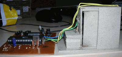
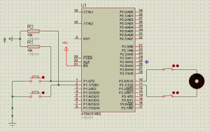
The main purpose of the circuit is to control the gate of the house. This DC motor and provided with two limit switches is provided by mechanical parts. The two buttons open and close the circuit inside is available. Sent to the ends of the drive motor integrated into 1 and 0 knowledge engine is turning left or right.
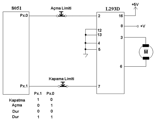
AT89C51RD2 switches are connected in series to the output port. As soon as the door closed one of the key information by sending port is disconnected. When the other button is pressed, this time the information is sent to one of the other ports and the engine returns to the other side and this time it is connected to the switch port opens.
L293D DC MOTOR DOOR CONTROL
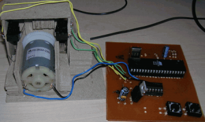
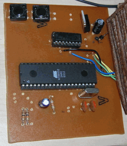
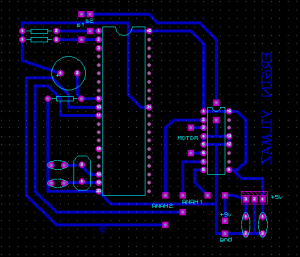
L293D DC MOTOR DOOR CONTROL SCHEMATIC PCB
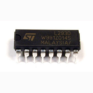
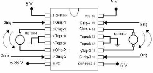
L293D PIN CONNECTING
Output Ports Connection Diagram with Motor Drive
Source: DC MOTOR WITH DOOR CONTROL CIRCUIT AT89C51 L293D DC Motor with Door Control proteus isis schematic pcb keil source code at89c51-l293d-dc-motor-with-door-control.rar
- What is the main purpose of this circuit?
The main purpose is to control the gate of the house. - How does the system detect when the door is closed?
As soon as the door closes, one of the keys by sending the port is disconnected. - Can the motor turn left or right based on input?
Yes, information sent to 1 and 0 knowledge engine makes it turn left or right. - Which components are connected in series to the output port?
AT89C51RD2 switches are connected in series to the output port. - What happens when the other button is pressed?
Information is sent to another port, the engine returns to the other side, and it connects to the switch port opens. - Does the project include mechanical parts?
Yes, the DC motor is provided with two limit switches by mechanical parts. - What software tools are mentioned for this project?
Keil example and proteus isis schematic pcb are mentioned alongside microcontroller projects. - Is there a source code available for download?
Yes, the source code is available in the file at89c51-l293d-dc-motor-with-door-control.rar.