Summary of ATMEGA8 BIPOLAR STEPPER MOTOR DRIVER CIRCUIT L293B
This project describes a bipolar stepper motor control circuit using an Atmega8 microcontroller and an L293B motor driver. Operating between 6V to 35V and capable of handling up to 1 amp, it features PWM control, UART communication, and includes source code, PCB designs, and simulation files. The system is intended for precise motor control applications utilizing Atmel's AVR technology.
Parts used in the Bipolar Stepper Motor Control Circuit:
- Atmega8 microcontroller
- L293B motor driver IC
- Bipolar stepper motor
- Power supply (6V to 35V)
- PCB board
- Supporting passive components (resistors, capacitors, etc.)
- Programming and sensor interface (for PWM and UART functionality)
Bipolar stepper motor control circuit 6v … 35v inter able to run power 1 amp on the circuit control, program, sensor, PWM, UART has links ATMega8 output used in motor drive l293b circuit of… Electronics Projects,ATMega8 Bipolar Stepper Motor Driver Circuit L293B “atmega8 projects, avr project, microcontroller projects, motor control circuit, motor driver circuit, “
Bipolar stepper motor control circuit 6v … 35v inter able to run power 1 amp on the circuit control, program, sensor, PWM, UART has links ATMega8 output used in motor drive l293b circuit of the source c code ares pcb and isis simulation files there. control circuit microcontroller atmel atmega8 motor control L293
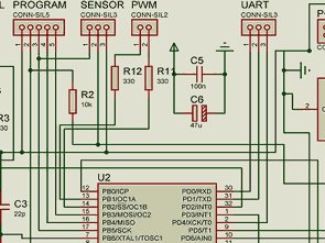
BIPOLAR STEPPER MOTOR CIRCUIT L293B
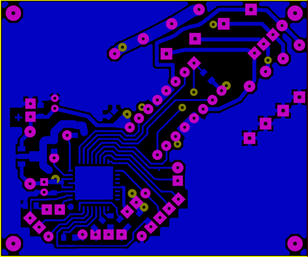
Source: http://railab.ru L293B ATmega8 step motor control circuit pcb, circuit, code files alternative link: atmega8-bipolar-stepper-motor-driver-circuit-l293b.rar