Summary of ATMEGA8 BIPOLAR STEPPER MOTOR DRIVER CIRCUIT L293B
This article describes a bipolar stepper motor control circuit powered between 6V and 35V, capable of driving up to 1A. The system utilizes an ATMega8 microcontroller interfaced with an L293B motor driver IC. Key features include support for PWM, UART communication, and sensor integration. The project provides downloadable source code, PCB layouts, and ISIS simulation files for implementation.
Parts used in the Bipolar Stepper Motor Control Circuit:
- Bipolar Stepper Motor
- ATMega8 Microcontroller
- L293B Motor Driver IC
- Power Supply (6V – 35V)
- Sensors
- PWM Module
- UART Interface
- PCB Board
- Source C Code
- ISIS Simulation Files
Bipolar stepper motor control circuit 6v … 35v inter able to run power 1 amp on the circuit control, program, sensor, PWM, UART has links ATMega8 output used in motor drive l293b circuit of… Electronics Projects,ATMega8 Bipolar Stepper Motor Driver Circuit L293B “atmega8 projects, avr project, microcontroller projects, motor control circuit, motor driver circuit, “
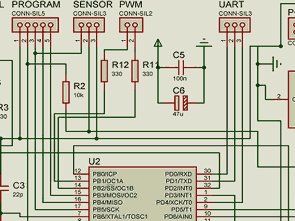
Bipolar stepper motor control circuit 6v … 35v inter able to run power 1 amp on the circuit control, program, sensor, PWM, UART has links ATMega8 output used in motor drive l293b circuit of the source c code ares pcb and isis simulation files there. control circuit microcontroller atmel atmega8 motor control L293
BIPOLAR STEPPER MOTOR CIRCUIT L293B
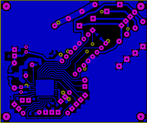
Source: http://railab.ru L293B ATmega8 step motor control circuit pcb, circuit, code files alternative link: atmega8-bipolar-stepper-motor-driver-circuit-l293b.rar
- What is the operating voltage range for this circuit?
The circuit operates within a power range of 6V to 35V. - How much current can the circuit drive?
The control circuit is able to run power up to 1 amp. - Which microcontroller is used in this project?
The project uses the Atmel ATMega8 microcontroller. - What motor driver IC is utilized in the design?
The L293B chip is used as the motor driver circuit. - Does the circuit support serial communication?
Yes, the circuit includes a UART interface for communication. - Can Pulse Width Modulation be used with this setup?
The circuit supports PWM functionality alongside other features. - Where can I find the source code and simulation files?
Files including source C code, PCB layouts, and ISIS simulations are available via provided links. - Is this project suitable for AVR development?
Yes, it is categorized as an AVR project involving microcontroller motor control.