
Summary of Adafruit Trellis Shield Latching Keyboard Test using ATmega328P with Proteus Simulation
This article describes a Proteus simulation of an Adafruit Trellis Shield latching keyboard using an ATmega328P microcontroller. The system utilizes I2C communication to toggle LEDs on a 4x4 keypad matrix when buttons are pressed, providing visual feedback and serial output. It serves as an educational tool for learning embedded systems, I2C protocols, and LED control logic without requiring physical hardware initially.
Parts used in the Adafruit Trellis Shield Latching Keyboard Test:
- ATmega328P microcontroller
- Arduino 328 compatible circuit
- Adafruit Trellis Shield
- HT16K33 LED/keypad controller
- 4x4 Trellis button matrix
- I2C SDA line
- I2C SCL line
- INT line connected to A2
- Reset push button
- Status LED
- Resistors
- 5V power supply
- Serial RXD/TXD connection
Introduction
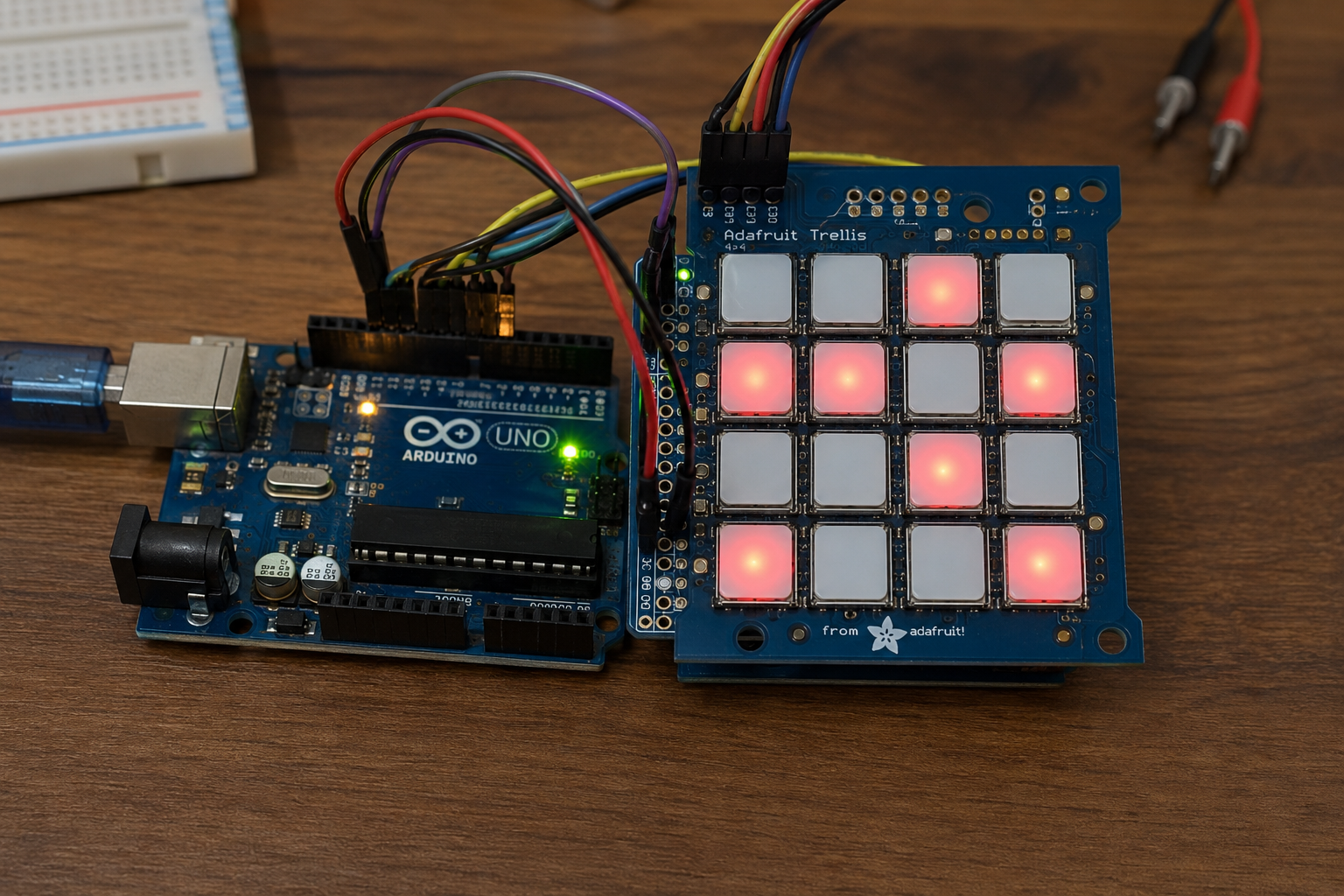
This project demonstrates an Adafruit Trellis Shield latching keyboard test using the ATmega328P controller in a Proteus simulation environment.
It is a simple but useful microcontroller project for learning how a keypad-style LED button matrix works with an Arduino-compatible AVR controller.
The system reads button presses from the Trellis keypad and toggles the matching LED on or off in latching mode.
It is a practical example for students and makers working with embedded systems, DIY electronics, I2C communication, keypad scanning, and LED control.
The simulation helps visualize the working principle, circuit diagram, and source code behavior before testing on hardware.
How the Project Works
The project uses an ATmega328P / Arduino 328 controller connected to an Adafruit Trellis Shield based on the HT16K33 controller.
The Trellis Shield communicates with the microcontroller using the I2C bus, so only the SDA and SCL lines are required for communication. In the provided code, the Trellis module is initialized at I2C address 0x70.
When the simulation starts, all Trellis LEDs turn on one by one and then turn off one by one. After that, the system enters latching mode. In this mode, pressing a button toggles its related LED:
- If the LED is off, pressing the key turns it on.
- If the LED is already on, pressing the key turns it off.
The code also sends key press information to the Serial Monitor at 9600 baud, printing the pressed key number.
Workflow Explanation
System Workflow
ATmega328P / Arduino 328
        |
        | I2C Communication
        | SDA + SCL
        |
HT16K33 Trellis Controller
        |
        | Scans keypad switches
        | Controls LED matrix
        |
Adafruit Trellis Shield
        |
        | User presses a button
        |
Firmware detects new press
        |
LED state toggles in latching mode
        |
Display buffer updates the LED output
Workflow Steps
- The ATmega328P starts the program and opens serial communication at 9600 baud.
- The Trellis INT pin is configured with a pull-up.
- The Trellis Shield is initialized at I2C address 0x70.
- All LEDs are switched on sequentially as a startup test.
- All LEDs are then cleared sequentially.
- The firmware continuously checks for switch changes.
- When a button is pressed, the code toggles the matching LED.
- The updated LED state is written back to the HT16K33 display buffer.
Key Features
- Uses ATmega328P AVR microcontroller.
- Designed for Arduino AVR compilation.
- Proteus VSM simulation for AVR.
- Supports Adafruit Trellis Shield.
- Uses HT16K33 I2C LED/keypad controller.
- Reads a 16-key Trellis button matrix.
- Controls 16 individual LEDs.
- Latching mode enabled by default.
- Momentary mode is also available in the code.
- Uses only SDA, SCL, and INT lines for Trellis communication.
- Serial output prints key press information.
- Supports expansion up to multiple Trellis matrices in the library.
Components Used
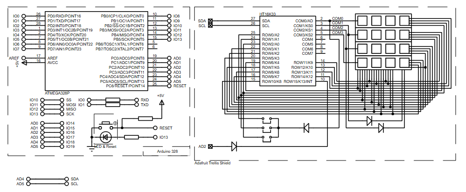
Based on the schematic diagram and source code, the project uses:
- ATmega328P microcontroller
- Arduino 328 compatible circuit
- Adafruit Trellis Shield
- HT16K33 LED/keypad controller
- 4×4 Trellis button matrix
- LED matrix connected through the Trellis Shield
- I2C SDA line
- I2C SCL line
- INT line connected to A2
- Reset push button
- Status LED
- Resistors
- 5V power supply
- Serial RXD/TXD connection
Applications
This type of embedded systems project is useful in many practical electronics designs, such as:
- DIY MIDI-style button controllers
- Interactive LED keypads
- Control panels for embedded devices
- Menu input panels
- User interface testing for Arduino projects
- LED feedback keyboards
- Educational AVR and Arduino simulations
- Button matrix scanning practice
- I2C communication learning projects
This project is not a temperature sensor project; it focuses on keypad input and LED feedback using the Adafruit Trellis Shield.
Explanation of Code
The firmware is written for the Arduino AVR environment and uses the Wire library for I2C communication.
Main Program
The main.ino file sets the project mode to LATCHING. This means every new button press toggles the LED state instead of keeping the LED on only while the button is held.
The setup function initializes:
- Serial communication at 9600 baud
- Trellis interrupt input on A2
- Trellis module at I2C address 0x70
- Startup LED test sequence
The loop function checks for button changes every 30 milliseconds. When a key is newly pressed, the firmware checks the current LED state and either turns it on or clears it.
I2C / Wire Module
The project uses I2C through the Arduino Wire library. The SDA and SCL lines connect the ATmega328P to the HT16K33 controller on the Adafruit Trellis Shield.
HT16K33 Trellis Library
The provided Adafruit_Trellis library handles:
- Key scanning
- LED mapping
- Display buffer updates
- Brightness control
- Blink rate control
- Multiple Trellis matrix support
UART / Serial Output
The code uses serial communication to print debugging messages. On startup, it prints:
Trellis DemoWhen a key is pressed, it prints:
v0
v1
v2
...
depending on the button number.
ADC, LCD, Timers, and Sensors
No ADC module, LCD, DSP processing, or temperature sensor is used in this project. The A2 pin is used as a digital interrupt-style input line for the Trellis INT signal.
Source Code
void loop() {
  delay(30); // 30ms delay is required, dont remove me!

  if (MODE == MOMENTARY) {
    // If a button was just pressed or released...
    if (trellis.readSwitches()) {
      // go through every button
      for (uint8_t i=0; i<numKeys; i++) {
        // if it was pressed, turn it on
        if (trellis.justPressed(i)) {
          Serial.print("v"); Serial.println(i);
          trellis.setLED(i);
        }
        // if it was released, turn it off
        if (trellis.justReleased(i)) {
          Serial.print("^"); Serial.println(i);
          trellis.clrLED(i);
        }
}Proteus Simulation
In the Proteus simulation, the ATmega328P is connected to the Adafruit Trellis Shield circuit. The schematic shows the Trellis section using the HT16K33 controller with SDA and SCL communication lines.
When the simulation runs, the project behaves like a latching LED keypad:
- The firmware starts and initializes the Trellis controller.
- The LEDs turn on in sequence as a startup check.
- The LEDs turn off in sequence.
- Pressing any Trellis button toggles the matching LED.
- Pressed key numbers are sent through the serial output.
This makes the simulation useful for testing the firmware, circuit diagram, I2C communication, and keypad response before building the actual hardware.
Conclusion
The Adafruit Trellis Shield Latching Keyboard Test using ATmega328P is a clean and practical microcontroller project for learning keypad scanning, LED control, and I2C communication in Proteus simulation.
It is especially useful for beginners working with Arduino-style AVR projects, embedded systems, and interactive DIY electronics.
With simple firmware and clear visual feedback, this project makes the working principle of a latching LED keypad easy to understand and test.
Complete File
Adafruit Trellis Shield Latching Keyboard Test using ATmega328P with Proteus Simulation
- How does the project work?
The system uses an ATmega328P connected via I2C to an HT16K33 controller that scans a 4x4 keypad and toggles corresponding LEDs in latching mode. - What is the function of the INT pin?
The INT pin is connected to digital input A2 and configured with a pull-up resistor to detect Trellis interrupt signals. - Can this project be used for temperature sensing?
No, the article explicitly states this is not a temperature sensor project but focuses on keypad input and LED feedback. - Does the code support multiple Trellis matrices?
Yes, the Adafruit_Trellis library supports expansion up to multiple Trellis matrices. - What happens when a button is pressed in latching mode?
Pressing a button toggles its related LED; if it is off it turns on, and if it is on it turns off. - Which library is used for I2C communication?
The project uses the Arduino Wire library for I2C communication between the microcontroller and the HT16K33 controller. - How often does the loop check for button changes?
The firmware checks for switch changes every 30 milliseconds. - What baud rate is used for serial communication?
Serial communication is opened at 9600 baud to print key press information to the Serial Monitor. - Is momentary mode available in the code?
Yes, while latching mode is enabled by default, the code also includes support for momentary mode.
