Summary of Bitmap Drawing on TFT LCD using ATmega328P with Proteus Simulation
This project demonstrates drawing bitmap images from an SD card onto a TFT LCD using an ATmega328P Arduino AVR setup in Proteus. It utilizes SPI communication to share the bus between the display and storage, supporting 24-bit uncompressed BMP files. The firmware initializes the screen with text, loads the image file, converts BGR pixel data to TFT color format, and renders the graphic, serving as an educational tool for embedded systems and DIY electronics learners.
Parts used in the Bitmap Drawing on TFT LCD using ATmega328P:
- ATmega328P controller
- Arduino AVR firmware
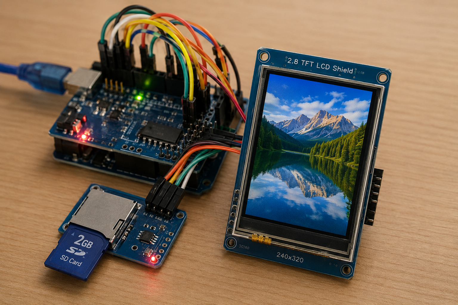
- 2.8-inch TFT LCD shield
- ILI9341 TFT LCD display
- SD card module / SD card socket
- SPI interface lines (MOSI, MISO, SCK)
- TFT chip select pin
- TFT data/command pin
- SD card chip select pin
- 3.3V voltage regulator
- Reset supervisor circuit
- Reset push button
- Level shifting / buffer circuitry
- STMPE610 touch controller
- Resistors
- Capacitors
- Diode
- NPN transistor
- 5V and 3.3V supply rails
Introduction
This microcontroller project demonstrates how to draw bitmap images on a TFT LCD using an ATmega328P-based Arduino AVR setup.
The image file is stored on an SD card and loaded directly onto the display through the SPI interface.
It is a useful Proteus simulation for learning how SD card storage, TFT LCD control, and embedded graphics work together.
This project is ideal for students and DIY electronics learners who want to understand practical electronics with display-based embedded systems.
It also gives a clear working principle for building simple image viewers, display dashboards, or graphical interfaces using source code and firmware.
How the Project Works
The project uses an ATmega328P controller programmed with Arduino AVR code. The TFT LCD and SD card share the hardware SPI bus. The SD card stores a bitmap file named image.bmp, and the firmware reads this file from storage.
Once the SD card is initialized, the TFT display first shows text on a blue background. After that, the program loads the bitmap image from the SD card and draws it on the TFT LCD.
The code supports 24-bit uncompressed BMP files. It reads the bitmap header, checks the image format, calculates row padding, and pushes pixel data to the ILI9341 TFT display.
Workflow Explanation
The simulation workflow is simple:
- ATmega328P / Arduino AVR controller starts the firmware
- SPI communication is initialized
- ILI9341 TFT LCD is started
- SD card is initialized using chip select pin 4
- Text is displayed on the TFT screen
- The file
image.bmpis opened from the SD card - BMP header information is checked
- Pixel data is read in small buffers
- RGB bitmap data is converted to TFT color format
- The image is drawn on the TFT LCD
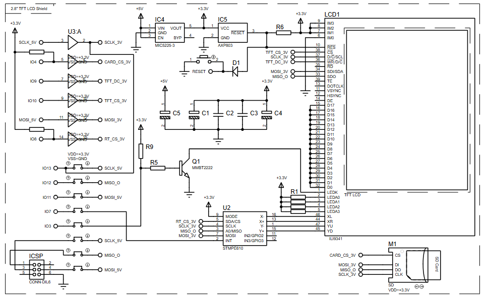
The schematic shows a TFT LCD shield, SD card socket, SPI lines, reset circuit, 3.3V regulation, level shifting, and supporting passive components.
Key Features
- Bitmap drawing on TFT LCD from SD card storage
- ATmega328P-based Arduino AVR microcontroller project
- Proteus simulation for embedded graphics testing
- Uses ILI9341 TFT LCD driver
- Uses SD card file reading through SPI
- Displays text and bitmap image output
- Supports 24-bit uncompressed BMP image files
- Reads BMP data using buffered pixel loading
- Includes serial monitor messages for SD card and BMP loading status
- Practical example for embedded systems and DIY electronics learning
Components Used
Based on the provided schematic and source code, the project uses:
- ATmega328P controller
- Arduino AVR firmware
- 2.8-inch TFT LCD shield
- ILI9341 TFT LCD display
- SD card module / SD card socket
- SPI interface lines: MOSI, MISO, SCK
- TFT chip select pin
- TFT data/command pin
- SD card chip select pin
- 3.3V voltage regulator
- Reset supervisor circuit
- Reset push button
- Level shifting / buffer circuitry
- STMPE610 touch controller shown in the schematic
- Resistors
- Capacitors
- Diode
- NPN transistor
- 5V and 3.3V supply rails
Applications
This type of Proteus simulation and firmware can be useful in:
- Embedded graphics learning projects
- TFT LCD interface testing
- SD card-based display systems
- DIY electronics image display projects
- Small graphical user interfaces
- Product display screens
- Educational embedded systems labs
- Arduino-based display experiments
- Bitmap image viewer projects
- Display firmware testing before hardware implementation
Explanation of Code
The code is written for the Arduino AVR platform and uses the ATmega328P controller.
TFT LCD Module
The project uses the Adafruit_ILI9341 library to control the TFT LCD. The TFT display is initialized in the setup() function, and the screen is filled with a blue background.
The display uses:
TFT_CS = 10TFT_DC = 9
The program also changes screen rotation and prints text using the graphics library.
SD Card Module
The SD card is initialized using the Arduino SD library. The SD card chip select pin is:
SD_CS = 4
The code checks whether the SD card starts correctly. If initialization fails, the serial monitor prints failed!. If successful, it prints OK!.
SPI Communication
Both the TFT LCD and SD card share the hardware SPI interface. According to the code comments, for Arduino Uno-style boards:
- Pin 11 = MOSI
- Pin 12 = MISO
- Pin 13 = SCK
This is a common working principle in many embedded systems where multiple SPI devices share the same bus but use separate chip select pins.
Bitmap Drawing Function
The bmpDraw() function handles the main image loading process. It opens the BMP file, reads the file header, checks the bitmap signature, reads image size and bit depth, and then draws the image pixel by pixel.
The code only accepts:
- BMP signature:
0x4D42 - 24-bit bitmap depth
- Uncompressed BMP format
The pixel data is read from the SD card in buffered chunks using:
#define BUFFPIXEL 20This reduces the number of SD card reads and improves drawing performance while keeping RAM usage manageable for the ATmega328P.
Color Conversion
BMP files store pixels in BGR order. The code reads blue, green, and red values separately, then converts them into the 16-bit color format required by the TFT display using:
tft.color565(r,g,b)The converted color is then pushed to the display.
Serial Debugging
The firmware prints useful debugging messages such as:
- SD card initialization status
- File loading status
- BMP file size
- Image offset
- Header size
- Bit depth
- Image dimensions
- Loading time
- BMP format errors
This helps with troubleshooting during Proteus simulation and hardware testing.
Source Code
#define SD_CS 4

void setup(void) {
  Serial.begin(9600);

  tft.begin();
  tft.fillScreen(ILI9341_BLUE);

  Serial.print("Initializing SD card...");
  if (!SD.begin(SD_CS)) {
    Serial.println("failed!");
  }
  Serial.println("OK!");
}Proteus Simulation
In the Proteus simulation, the ATmega328P-based Arduino AVR firmware controls a TFT LCD shield and reads bitmap data from an SD card. The TFT display first shows a blue screen with the text:
Designed with
Proteus VSM
After that, the simulation loads image.bmp from the SD card and draws it on the TFT LCD. The serial output is used to show whether the SD card initialized correctly and whether the BMP file was loaded successfully.
If the image file is missing, the serial monitor reports:
File not foundIf the BMP format is unsupported, the firmware reports:
BMP format not recognized.Conclusion
This ATmega328P TFT LCD bitmap drawing project is a strong practical electronics example for learning display control, SD card access, SPI communication, and basic graphics handling. The Proteus simulation makes it easier to understand the circuit diagram and firmware behavior before testing on real hardware. For embedded systems learners and DIY electronics builders, it is a useful project for moving beyond simple text output and into graphical display applications.
Complete File
Bitmap Drawing on TFT LCD using ATmega328P with Proteus Simulation
- How does the project load images?
The firmware reads a 24-bit uncompressed BMP file named image.bmp from the SD card via the SPI interface and draws it on the ILI9341 TFT LCD. - What controller is used in this simulation?
The project uses an ATmega328P-based Arduino AVR microcontroller programmed with specific firmware. - Which library controls the TFT LCD?
The Adafruit_ILI9341 library is used to initialize and control the TFT LCD display. - What are the required SPI pins for Arduino Uno-style boards?
Pin 11 is MOSI, Pin 12 is MISO, and Pin 13 is SCK. - Can the system handle compressed BMP files?
No, the code only accepts 24-bit uncompressed BMP format files. - How does the code manage memory during image loading?
The code reads pixel data in buffered chunks of 20 pixels to reduce SD card reads and keep RAM usage manageable. - What happens if the SD card initialization fails?
The serial monitor prints failed! to indicate that the SD card did not start correctly. - How is color conversion handled for the display?
The code reads BGR values from the BMP file and converts them to 16-bit color format using tft.color565(r,g,b). - What message appears if the image file is missing?
The serial monitor reports File not found if the image.bmp file cannot be located on the SD card. - What is the purpose of the Proteus simulation in this context?
The simulation allows users to understand the circuit diagram and firmware behavior before testing on real hardware.