Summary of Attiny13A Motor Controller Board
This project describes a motor controller board using an ATtiny13A to PWM-control an IRFZ44N N-channel MOSFET for a brushed DC motor. A single button cycles three modes: full speed, half speed, and off. The board includes a 5V AMS1117 regulator, PCB fabrication at Seeed Studio, SMD assembly with reflow, and final THT additions. The design targets a bladeless fan project, supports up to 55V/49A MOSFET ratings (heatsink advised), and uses a simple compact sketch to implement the tap-based modes.
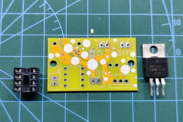
Parts used in the Motor Controller board:
- Attiny13A
- Custom PCB
- Brushed DC Motor
- IRFZ44N N-channel MOSFET
- AMS1117 5V voltage regulator
- 10K resistor
- 1 µF capacitor
- 10 µF capacitor
- DIP socket (for ATtiny13A)
- Tactile switch
- SMD LED
- Battery connector
- Barrel DC jack (charging port)
- Solder paste (for assembly)
- Optional heatsink
So here’s something super interesting and useful, a motor controller board powered by an Attiny13A to control a Brushed DC Motor.
This Motor Driver uses PWM to control the gate of an N Channel IRFZ44N mosfet by the Tap of a single button.
I’ve added Two Modes in the code that basically controls the Duty Cycle, On First Tap the setup turns ON at 100% Duty cycle, then on the Second Tap, the Duty Cycle is half at 50%. The third Tap turns the whole setup OFF.
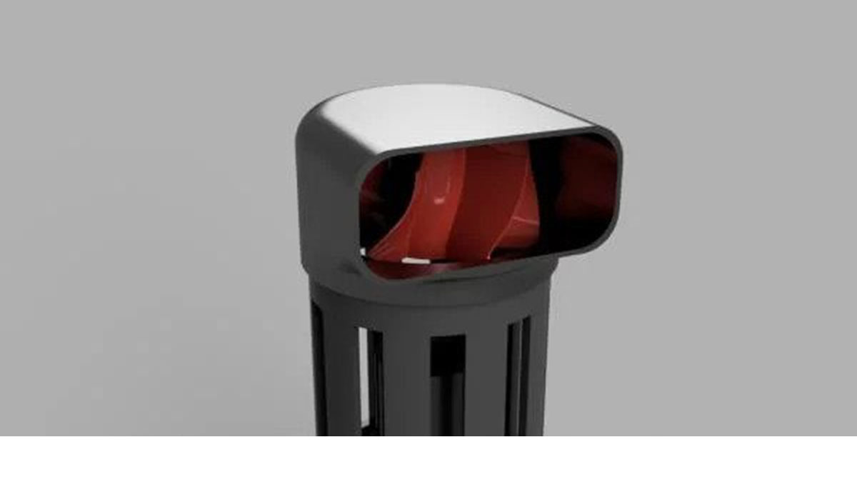
I made this Motor Controller board for a future project that is a Bladeless Fan Project that I will soon publish.
This Instructables is about the whole building process of this Motor Controller so let’s get started!
Supplies
Following were the materials used in this project-
- Attiny13A
- Custom PCB
- Brushed DC Motor
- IRFZ44N
- AMS1117 5V
- 10K Resistor
- 1uf Capacitor
- 10uf Capacitor
Step 1: SCHEMATIC and PCB Design
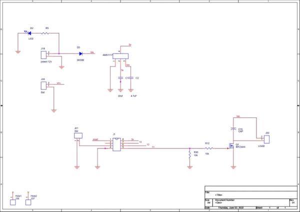
This Schematic is a simple one, there’s an N Channel Mosfet that is configured in “Mosfet as Switch setup”. This means the gate of Mosfet can be used to power the load which is, in this case, a DC Brushed Motor.
There are two Resistors connected to the Gate of Mosfet, one is connecting the gate with GND and another one is connected to the D0 Pin of Attiny13A.
I’ve used an Attiny13A to control the whole setup by using a Switch that is connected to the D4 pin and GND. By connecting D4 Pin to GND, Microcontrollers read this and provide the gate of Mosfet with a PWM signal that controls the gate of mosfet and the speed of the motor.
Now, the motor that I’m using works at 12V and above but the microcontroller needs 5V Input so to step down 12V into 5V for MCU, I’ve added an AMS1117 5V Voltage Regulator.
As for programming pins for Attiny13, I haven’t added any. Because I’m using the DIP version of attiny and I’m planning to flash attiny with my Attiny programmer that has DIP Socket for flashing the MCU.
I finalise the Schematic and prepared the PCB according to the PCB Outline that is required in my BLADELESS FAN Project.
Step 2: Getting PCBs From SEEED Studio
After finalizing the PCB and generating its Gerber data, I send it to SEEED STUDIO for samples.
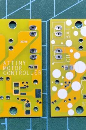
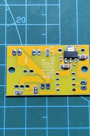
Ordered PCBs in Yellow Soldermask with white silkscreen.
I received PCBs in a week and their quality was super good considering the rate which was also pretty low.
Seeed Fusion PCB Service offers one-stop prototyping for PCB manufacture and PCB assembly and as a result, they produce superior quality PCBs and Fast Turnkey PCBA within 7 working days.
PCB Quality of this Motor Controller PCB WAS SUPER!
Seeed Studio Fusion PCB Assembly Service takes care of the entire fabrication process from PCB manufacturing, parts sourcing, assembly, and testing services, so you can be sure that they are getting a quality product.
After gauging market interest and verifying a working prototype, Seeed Propagate Service can help you bring the product to market with professional guidance and a strong network of connections.
Step 3: PCB ASSEMBLY
PCB Assembly of this project consists of four major steps which are
- Solder Paste Dispensing Process
- Pick & Place Process
- Hotplate Reflow
- Adding THT Components
Step 4: Solder Paste Dispensing Process
We start first by adding Solderpaste to each component pad on the bottom side of the board.
Step 5: Pick & Place Process
Then we pick and place each component in its assigned place one by one.
Step 6: Hotplate Reflow
Next, we carefully lifted the whole PCB and place it on the hotplate. I’m using my good old DIY hotplate which I made a while back.
Hotplate Heats the surface up to the solder paste melting temp and it slowly melts. after a few mins when the solder paste completely melts, we remove the PCB and let it cool down for a moment.
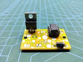
Step 7: Adding THT Components
Here’s the final setup, we place the remaining two components which are DIP Socket and Mosfet. However, we also add an SMD LED on the Top side with a soldering Iron as well, we cannot use a hotplate for placing the LED as we already place stuff on the Bottom side and this hotplate method is applicable for one side only.
Step 8: Attiny13A and Main Code
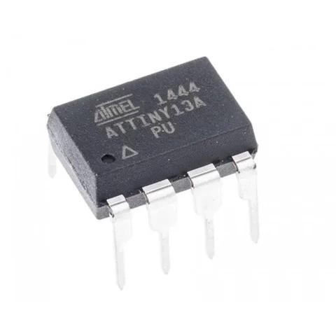
Attiny13 is a low-power Microchip 8-bit AVR® RISC-based microcontroller that combines 1 KB ISP Flash memory, 64B SRAM, 64B EEPROM, a 32B register file, and a 4-channel 10-bit A/D converter.
I’ve used Attiny13A in this project instead of the more popular Attiny85, here’s why.
The sketch that I’m using is a pretty small sketch of size 296 bytes and Attiny13A has a total of 1024 bytes which is plenty even if we increased the functions in the preexisting sketch.
const int switchPin = 4;
const int FANPin = 0;
int FANMode = 1;

void setup()
{
    pinMode(FANPin, OUTPUT);
    pinMode(switchPin, INPUT_PULLUP);
    digitalWrite(FANPin, LOW);

}
void loop()
{
    if (digitalRead(switchPin) ==LOW)
    {
        FANMode = FANMode + 1;
        if (FANMode == 4)
        {
            FANMode = 1;
        }
    }
    if (FANMode == 1)
    {
        digitalWrite(FANPin, LOW);
        delay(200);
    }
    else if (FANMode == 2)
    {
        digitalWrite(FANPin, HIGH);
        delay(200);
    }
    else if (FANMode == 3)
    {
        analogWrite(FANPin, 50);
        delay(200);
    }
    //delay(200); // see text
}
Attiny85 is a much more advanced MCU with 8 KB ISP Flash memory, 512B EEPROM, 512B SRAM. It’s suitable for more demanding projects like running two or three servos at the same time with three I/O Pins or driving Neopixels.
It would be overkill to use an Attiny85 to run a single motor with a button so that’s the main reason for using Attiny13A.
Also, Attiny13A is inexpensive compared with an Attiny85.
As for the flashing process of Attiny13A, check out this post of mine for more details.
https://www.instructables.com/Multiple-ATtiny8513A-Programmer/
After burning the bootloader and uploading the sketch in the ATtiny13A, we place the Attiny in its DIP Socket and move onto the final assembly of the board.
Step 9: FINAL ASSEMBLY STEP 1- Adding Switch
We start by adding a Tactile switch to the circuit’s Switch Connector.
A CN2515 connector can also be used instead of direct soldering the switch.
Step 10: STEP 2- Adding Motor
Next, we add DC Motor to its assigned connector pins, I’m manually soldering the wire instead of using a connector, the main and final version that I will use in my Bladeless Fan project will have connectors and wire harness and won’t have any solder joints.
Step 11: STEP 3- Adding Battery
We then add the battery’s Positive and Negative terminals to the battery connector in the right polarity. Now the circuit is alive. However, there’s the last thing left to add which is the charging port.
Step 12: STEP 4- Adding Charging Port
At last, we add a barrel DC Jack to the charging port so we can later add a 12V Adaptor for charging the battery.
Step 13: RESULT
Here’s the result.
As soon as we press the switch, the motor turns ON at max speed.
The second Tap reduces its speed by 50%, the third Tap turns everything OFF.
Its working is pretty simple and if we want, we can add more modes like increasing the Motor Speed by adding more Tap function that increases or decreases the speed of the motor.
Because we are using IRFZ44N Mosfet, we can drive the motor up to 55V at 49A which is insane but it would require a huge heatsink as we increase the motor power.
In my case, Motor Draws 12V at 0.500A at High Mode which is pretty low and sufficient for my application.
As for the alternate use for the circuit, we can use this circuit in anything that operates over 5V, Lights, motors, and even resistive elements.
Just make sure to add a heatsink if the load is heavy.
All the Docs related to the project are attached. If you need any help regarding this project, DM me or comment.
Special thanks to Seeed Studio for providing PCBs for this project. Do check them out if you need great PCB Service for less cost.
Source: Attiny13A Motor Controller Board
- How does the button control motor speed?
The single button cycles FANMode: first tap sets 100% duty (on), second tap sets 50% duty (analogWrite 50), third tap turns the motor off. - Does the board require a separate power supply for the microcontroller?
Yes, the AMS1117 5V regulator steps down the motor supply (12V) to 5V for the ATtiny13A. - Can the MOSFET handle high voltage and current?
The IRFZ44N can drive up to 55V at 49A but a large heatsink is required for heavy loads. - How is the ATtiny13A programmed?
The ATtiny13A DIP is programmed using a DIP-capable ATtiny programmer; no programming pins are included on the PCB. - What assembly processes were used for the PCB?
Assembly steps were solder paste dispensing, pick and place, hotplate reflow, and adding through-hole components manually. - Can this controller be used for other loads besides motors?
Yes, it can be used for devices operating over 5V such as lights, motors, or resistive elements, with a heatsink for heavy loads. - Why use ATtiny13A instead of ATtiny85?
Because the sketch is small (296 bytes) and ATtiny13A has sufficient flash (1 KB), making it lower cost and sufficient for a single motor control. - What happens when the board is powered and the switch is pressed?
First press turns motor to max speed, second press reduces speed by ~50%, third press turns it off.