The ATtiny84 is a truly amazing chip, not quite an Arduino, but in some ways much more powerful. This is a small project designed to show off it’s potential.
All Atmel microcontrollers have their pins mapped in banks of eight, whether all eight pins are present or not. For instance the ATtiny85 is an eight pin chip with five digital pins. The ATmega328P chip in an Arduino has three banks of pins but none of the banks have all eight pins available. The ATtiny84 has a total of eleven digital pins and all eight pins on one bank (A) are available.
Each bank of eight pins is controlled by three eight bit registers. The Data Direction Register (DDR), the PIN and the PORT registers. In the DDR register the bit is clear (0) if the pin is to be used as an input, and set (1) if it is an output. You read the PIN register when you do a digitalRead, and you do write to the PORT register when you do a digital write. If a pin is clear for input and it’s PORT bit is set this turns on the internal pull-up resistor. It is possible to write directly to the registers from the Arduino IDE and affect all eight pins at once. In many cases this can make a program easier to code and the compiled program will be much smaller.
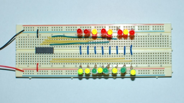
This program shows how easy it is to write a binary counter that counts up and down at the same time. The red LEDs are counting up while the green LEDs count down.
You will need:
- ATtiny84 https://www.sparkfun.com/products/11232
- An Arduino https://www.sparkfun.com/products/11021 (Used both as a programmer for the ATtiny84 and as a power supply.)
- Breadboard https://www.sparkfun.com/products/12615
- 8 Red LEDs https://www.sparkfun.com/products/9590
- 8 Green LEDs https://www.sparkfun.com/products/9592
- 16 470 Ohm resistors (Purchased locally)
- 22 gauge Hookup wire (Purchased locally)
Step 1: Adding the ATtiny Chip Definitions to the Arduino IDE
You will need to have the Arduino IDE installed on a computer to program the ATtiny84 chip. Go to https://www.arduino.cc/en/Main/Software to download the Arduino IDE. There are instructions here to install it on Linux, Windows, or Mac machines. If you are using Debian or Ubuntu it is in the repositories, just open a terminal and type:
sudo apt-get install arduino
Next you need to download the chip definition files for the ATtiny chip. They are available at:
You will get a zip file named attiny-master.zip, unzip it and you will have a directory named attiny-master. Inside the attiny-master directory there is a directory called attiny, this is the one you are looking for.
The Arduino software stores your programs and some other stuff in a directory called sketchbook.
Open the sketchbook directory and look for a directory called hardware. If it does not exist create it.
Copy the attiny directory into the hardware directory.
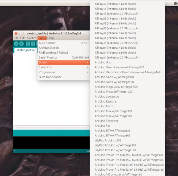
Check to make sure the Arduino IDE is finding the chip definitions by opening the Arduino IDE and clicking on Tools and then click on Board. It should look like the picture, you should see three entries to run the Attiny84 chip at 1, 8, or 20 MHz. There are also 3 entries each for the Attiny85, Attiny45, and Attiny44.
Step 2: The Program
/**********************************************************
 * Filename: UpDown.ino
 *
 * A binary counter program for ATtiny84
 **********************************************************/
void setup()
{
  DDRA = B11111111; // Set all 8 pins on A bank to output.
}

void loop()
{
  for(int i=0;i<256;i++)
  {
    PORTA = i; // Turn all 8 pins off/on at once.
    delay(250);
  }
}
Step 3: Uploading the Program to the ATtiny84

               ATtiny84
             Five Volts - 1  U  14 - Ground
                          2     13
                          3     12
      Pin 10 on Arduino - 4     11
                          5     10
                          6      9 - Pin 13 on Arduino
      Pin 11 on Arduino - 7      8 - Pin 12 on Arduino
Open the Arduino IDE and click on File=>Examples=>ArduinoISP.
Click on Tools=>Board and select the Arduino you are using. (In most cases, including my own, this will be Arduino Uno.
Click on Tools=>Programmer and select AVRISP mkII.
Click on the upload button. (The right arrow button second from the left.)
Place the Attiny84 on a breadboard and connect the wires as shown in the diagram.
Click on Tools=>Board and select ATtiny84 (internal 1 MHz clock).
Click on Tools=>Programmer and select Arduino as ISP.
Click on the upload button.
There is no reason to run the chip at a higher clock speed, all that will do is use more electricity. If you have changed the clock speed use the Tools=>Burn Bootloader option to reset the chip to 1 MHz before programming the chip. The burn bootloader option does not actually burn a bootloader on the ATtiny. It just changes the internal fuses to set the clock speed and a few other settings you don’t need to worry about. If you are using a new chip there is no need to burn the bootloader, the chip comes set the way you want it. Copy/Paste the program listed in step 2 into the Arduino IDE and click on the upload button.
Step 4: LED and Resistor

The picture shows a resistor soldered onto an LED. This is optional, but I found that having a bunch of these made up makes breadboarding a lot easier. Solder a resistor to the cathode lead of some LEDs. The cathode lead is the shorter negative (ground) lead. 270 – 560 ohms works good for on the RaspberryPi, for an Arduino use 330 – 680 ohm resistors. I usually make them with 470 – 560 ohm resistors so they will work with both.
You will need to make these with eight red and eight green LEDs for this project.
Step 5: Assemble the Circuit

The diagram does not show the resistors on each LED.
On the red LEDs the cathode (resistor lead) goes to ground and the anode goes to the pin. On the green LEDs the cathode goes to the pin and the anode to the positive rail. When the pin is high the red LED will bit lit and when it is low the green LED will be lit.
The pink mark on the IC chip indicates pin one.
The Arduino is used as a power supply.
Here is a list of the digital pins and the Arduino Pin numbers:
             ATtiny84
             Five Volts - 1  U  14 - Ground
        Arduino 10, PB0 - 2     13 - PA0, Arduino 0
         Arduino 9, PB1 - 3     12 - PA1, Arduino 1
                          4     11 - PA2, Arduino 2
         Arduino 8, PB2 - 5     10 - PA3, Arduino 3
         Arduino 7, PA7 - 6      9 - PA4, Arduino 4
         Arduino 6, PA6 - 7      8 - PA5, Arduino 5
This link http://42bots.com/tutorials/programming-attiny84-a… has the full pinout chart for the Attiny84. I am not including the picture because I don’t know the copyright status.
Source: ATtiny84 Binary Counter, Up and Down