Summary of ATtiny85 Interrupt Barebones Example
This article provides a simplified guide to configuring an AVR ATtiny85 for external interrupts. The project detects voltage changes on pin 6 (PB1) and triggers an interrupt service routine that sets an LED on pin 3 (PB4) to match the input state. The author created this "barebones" example because existing tutorials were often too complex or incomplete, offering a streamlined code and circuit solution using standard components.
Parts used in the ATtiny85 Interrupt Project:
- AVR ATtiny85 processor
- Breadboard
- LED
- Resistor (300 to 2.5k ohms)
- Momentary switch
- Jumper wires
- 5v power supply
This example code and simple wiring demonstrated how to setup an AVR ATtiny85 processor to react to external interrupts. Whenever the voltage changes on the chosen input pin (pin 6 / PB1), it executes the interrupt service routine (ISR), checks the current voltage, and sets the output pin (pin 3 / PB4) to match. This is visible because of an LED (with current limiting resistor) attached to the output pin.
I needed this setup because examples of how to configure an ATtiny85 to enable interrupts are often complex or incomplete. After reading several sites, processor documentation, and learning more about the platform, I was able to clean up and distill down a couple of examples I found into one single nearly-barebones code and circuit example.
Supplies
AVR ATtiny85 (PDIP package in this example)
breadboard
LED
Resistor (any value 300 to 2.5k ohms should work fine)
Momentary switch
Jumper wires
5v power supply (I was using a USB power supply)
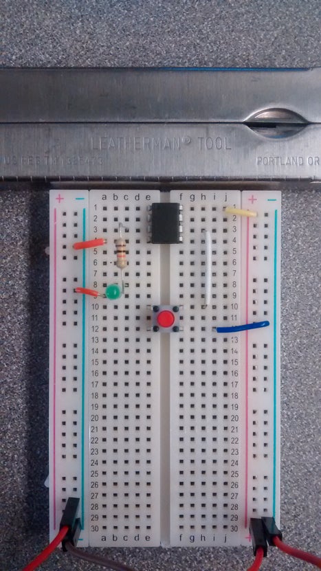
Step 1: Program the ATtiny85 and Wire the Board
The key piece of code to enable the interrupts lives here:
// Requires headers for AVR defines and ISR function
#include <avr/io.h>
#include <avr/interrupt.h>
#define INTERRUPT_PIN PCINT1  // This is PB1 per the schematic
#define INT_PIN PB1           // Interrupt pin of choice: PB1 (same as PCINT1) - Pin 6
#define LED_PIN PB4           // PB4 - Pin 3
#define PCINT_VECTOR PCINT0_vect      // This step is not necessary - it's a naming thing for clarit

void setup() {
  pinMode(LED_PIN, OUTPUT);
  cli();                            // Disable interrupts during setup
  PCMSK |= (1 << INTERRUPT_PIN);    // Enable interrupt handler (ISR) for our chosen interrupt pin (PCINT1/PB1/pin 6)
  GIMSK |= (1 << PCIE);             // Enable PCINT interrupt in the general interrupt mask
  pinMode(INT_PIN, INPUT_PULLUP);   // Set our interrupt pin as input with a pullup to keep it stable
  sei();                            //last line of setup - enable interrupts after setup
}
// This is the interrupt handler called when there is any change on the INT_PIN
// ISR is defined in the headers - the ATtiny85 only has one handlerISR(PCINT_VECTOR)
{
  if( digitalRead(INT_PIN) == HIGH ) {
    digitalWrite(LED_PIN, HIGH);
  }else{
    digitalWrite(LED_PIN, LOW);
  }
}
That code alone will run, but the attached .ino file has more comments, features and setup information.
Source: ATtiny85 Interrupt Barebones Example
- What happens when voltage changes on the chosen input pin?
The microprocessor executes the interrupt service routine to check the current voltage. - How is the output pin configured to match the input?
The ISR sets the output pin to HIGH if the input is HIGH, and LOW otherwise. - Which specific pin is used as the interrupt input in this example?
Pin 6, which corresponds to PB1 or PCINT1, is used as the interrupt pin. - Can I use any resistor value for the LED?
Any value between 300 and 2.5k ohms works fine for the current limiting resistor. - Why did the author create this specific example?
Existing examples were often complex or incomplete, so this one was distilled into a nearly barebones version. - What function disables interrupts during the setup phase?
The cli() function is used to disable interrupts while the configuration is being set up. - How do you enable the general interrupt mask after setup?
The sei() command is called as the last line of the setup function to enable interrupts.