
Summary of Audio Tone Generator using AVR Microcontroller
This project generates an audible tone using an AVR Microcontroller (ATMega32) to drive a speaker. The microcontroller outputs digital data representing sine wave values, which are converted to analog signals by a DAC0808. An LM741 op-amp converts the current output to voltage, and a TDA7056 amplifier drives an 8-ohm speaker to produce sound around 1W to 3W. The system operates on a 5V supply with a -12V requirement for the DAC, controlled by C code running at 16MHz.
Parts used in the Audio Tone Generator:
- AVR Microcontroller ATMega32
- 8-bit DAC DAC0808
- OP-AMP LM741
- Audio Amplifier TDA7056
- 8 Ohm Speaker
- 16 MHz Crystal
- 2 Capacitors of 22 pF
- 5K Resistors
- 5K Potentiometer
- General purpose PCB and Bread board
The circuit presented here demonstrates how to generate Audible Frequency from an AVR Microcontroller. The output of Microcontroller is always digital so to generate audible sound at the outset first it needs to be converted into Analog. A DAC (Digital to Analog Converter) is used for this purpose. Microcontroller generates sine wave of Audible Frequency using DAC. This sine wave is further given to Audio Amplifier that drives speaker. Microcontroller generates sine wave of fix frequency continuously. So we can hear an audible tone of fix frequency.
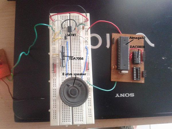
The photograph given below shows the circuit is built on general purpose PCB and bread board.
As shown in figure the major building blocks are AVR Microcontroller ATMega32, 8-bit DAC DAC0808, OP-AMP LM741 and Audio Amplifier TDA7056
AVR Microcontroller
AVR Microcontroller gives Digital values to DAC to generate sine wave output through it.
DAC0808
It converts digital values given by ATMega32 into Analog and generates continuous type sine wave
OP-AMP LM741
DAC0808 gives output in form of current. OP-AMP works as I to V converter and converts it in to voltage
Audio Amplifier
Audio Amplifier amplifies the signal given by OP-AMP so that it can drive speaker and generates sound output of around 1W to 3W
Circuit & Programming Description
Circuit Description
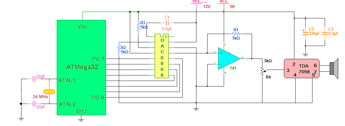
As shown in Circuit Diagram, PORTC pins PC0 – PC7 of ATMega32 are connected to digital inputs D0-D7 of DAC0808 respectively.
8Vref+ pin (14) of DAC0808 is connected to 5V through 5 K resistor that will generate Iref of 1 mA.
Vref- pin (13) is connected to ground through another 5K resistor.
The current output pin (4) of DAC is connected to non inverting input pin (3) of op-amp LM741. Inverting terminal of op-amp is grounded. A 5 K resistor is connected between Input and Output of op-amp as shown. Output of op-amp is given to input of Audio Amplifier through 5 K pot. Pot works as volume control. Audio Amplifier TDA7056 does not require any external components.
An 8 Ohm speaker is connected to output terminals 6 – 7 of TDA7056. All the chips works on 5 V so complete circuit is given power through 5 V supply.
DAC0808 needs -12 v supply for its –Vee pin (2).
A 16 MHz crystal along with 2 capacitors of 22 pF is connected to crystal input pins of ATMega32.
Circuit Operation
Microcontroller generates sequence of Digital Data in such a manner that a sine wave of Audio Frequency is generated through DAC0808 and op-amp. The output of op-amp is not pure sine wave but its staircase type sine wave as shown in photograph below.
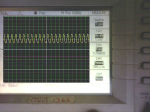
This sine wave is further amplified by Audio Amplifier chip. This chip drives 8? speaker and generates sound output of around 1 W.
Software Program
A software program written in C language is embedded into ATMega32 Microcontroller that will give sequence of data on PORTC to generate sine wave through DAC and op-amp. The program is edited, compiled and simulated in AVR studio software tool. Please refer the code for complete program with comments
Project Source Code
###
#include<avr/io.h>
#include<util/delay.h>

unsigned int sine_value[25] = {128,150,172,192,210,226,255,226,210,192,172,150,128,105,84,64,45,30,0,30,45,64,84,105,128};

void main()
  {
int i;
DDRC = 0xFF;  // declare PORTC as output
PORTC = 0x00;  // clear port
while(1)   // continuously send values to PORTC
   {
  for(i=0;i<25;i++)  // in loop
    {
   PORTC = sine_value[i];  // send values from sine wave table
   _delay_us(15); // adjust delay to get frequency of 1 KHz
    }
   }
  }
###
Project Video
For more detail: Audio Tone Generator using AVR Microcontroller
- How is the digital signal from the microcontroller converted to analog?
A DAC0808 converts the digital values given by the ATMega32 into analog to generate a continuous sine wave. - What component acts as a current to voltage converter?
The OP-AMP LM741 works as an I to V converter to change the DAC output current into voltage. - Can the volume be adjusted in this circuit?
Yes, a 5K pot connected between the op-amp output and audio amplifier input works as volume control. - What power supply voltages are required for the chips?
All chips work on 5V, but the DAC0808 needs a -12V supply for its negative Vee pin. - Does the audio amplifier require external components?
No, the Audio Amplifier TDA7056 does not require any external components. - What frequency does the generated sine wave operate at?
The program adjusts the delay to generate a frequency of 1 KHz. - What is the expected sound output power?
The amplifier drives the speaker to generate a sound output of around 1W to 3W. - Which software tool is used to edit and compile the program?
The program is edited, compiled, and simulated in the AVR studio software tool.
