Introduction
Several studies have shown that various insects possess learning and memory abilities. One approach researchers use to demonstrate such abilities is to “teach” the insect to exhibit a specific behavior in response to a stimulus. This “teaching” process is called Pavlovian conditioning. Such studies are often difficult to conduct because they require accurate timing of stimuli application and many trials to obtain significant results. In addition, data analysis is extremely tedious.
A system was previously developed at Hoy Lab, under the Cornell Neurobiology and Behavior department, for electronically automating Pavlovian conditioning of an insect species with minimal human involvement (due to confidentiality issues, we are unable to disclose the species at this time). The goal of our project was to improve this system by porting the controller from a National Instruments PCI-6070E data acquisition card, to an Atmel mega644 microcontroller. This involved programing the mega644 to perform time-dependent and sensor driven control of motors, stimuli, and video recording, as well as serial communication between a microcontroller and Matlab graphical user interface (GUI). The resulting system was significantly less expensive and more flexible; however, we sacrificed ADC performance in the process. This was reasonable trade-off since we expect that the mega644 ADC will be sufficient for the future implementation of physiological recording.
High Level
The main rationale of this project is to facilitate a simple and cost-effective means of reproducing conditioning experiments with insects. Previously, a more costly and less flexible solution was in place, using a National Instruments data acquisition card (PCI-6070E) as a controller. The system requires the PCI card, a shielded cable, and a connector block, all of which cost around $3000. In addition, this system only has 8 digital I/O pins which must have their I/O directions set together as a group. Our system replaces PCI-6070E with an Atmel Mega644 microcontroller. Not only is the cost significantly cheaper (around $30), the Mega644 has 32 bidirectional digital I/O pins which can be set individually. This eliminated the need for several ICs in the previous implementation (e.g. the 7400 inverter and 7402 NOR chips) and granted control of additional inputs to step motor ICs, which were formerly hardwired to constant values due to the lack of pins. By switching to the Atmel mega644, we lost the higher performance ADC available on the PCI-6070E. This was reasonable trade-off since we expect that the mega644 ADC will be sufficient for the future implementation of physiological recording. Figure 1 pictures the two controllers.
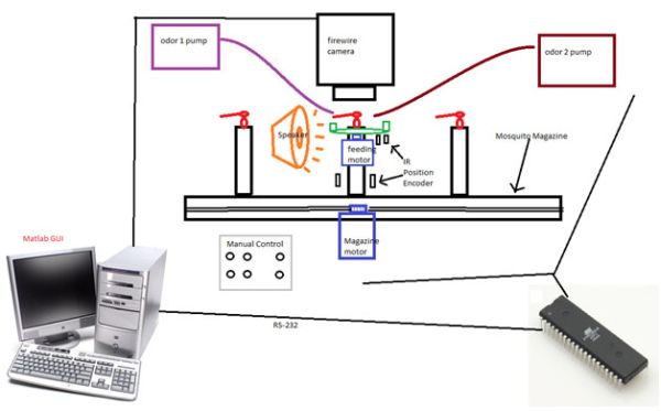
Our project consists of a GUI, implemented in Matlab, that communicates with the mega644 microcontroller through an RS-232 connection. Mechanically, the automating system consists of a feeding apparatus, insect magazine, and stimuli apparatus. A step motor rotates a feeding station. The feeding station is a plastic disk with one or two syringes containing a sucrose solution used to feed the insects. Another step motor is used to move a magazine which contains several insect restraining mechanisms. Each motor is provided with position feedback through an IR emitter and detector pair. The IR sensors trigger an external interrupt ISR to stop the motors at the appropriate position.
More specifically, for the feeding station, four small plastic slits are attached to the bottom of the disk spaced 90 degrees apart. These slits block IR sensor light and trigger an ISR which stops the motor. The insect magazine works in a similar manner. When the magazine stepper motor moves an new insect into position, it blocks the IR sensor light and stops the motor in front of the feeding mecahnism. The magazine is oriented so that in its stop position, only one insect can be fed at a time. For stimulis application, the mega644 digitally controls two odor pumps and an LED light. Sound stimuli are generated in Matlab. Matlab is also used to control video data acquisition. Figures 2,3,4 and 5 depict the entire system.
The Matlab GUI allows the user to design experiments. A typical conditioning experiment consist of moving insects one at a time to a position where it can be fed. Then a neutral stimulus such as odor or sound is applied, simultaneously, behavior is recorded via a video camera. Following the stimulus, the feeder station is rotated so that the sucrose solution is in position for the insects to be fed. After a specified amount of time, the feeder is rotated away, the video recorder is turned off, and the insect magazine is moved forward to repeat the experiment for the next insect. In addition to the conditioning experiment described above, a wide variety of other experiments can be conducted by specifying different stimuli, timing, and trial attributes.
The Matlab GUI communicates with the microcontroller through RS-232 by sending commands that we defined. The microcontroller parses these commands and controls the hardware accordingly. Some examples of commands include setting the motor speed, changing the motor direction, and turning on the odor pump etc. The Matlab GUI is picture in figure 4.
The mega644 microcontroller acts as a slave to a Matlab GUI. The GUI allows the user to intuitively design a wide variety of experiments. As depicted in figure 6, the user designs an experiment by entering the start and end time for each event he wants to occur during the experiment. An experiment is defined as the sequence of events that each insect will be individually subjected to. For each experiment, the user must specify the number of trials and number of insects on the magazine. The user is also allowed to perform several different experiments, one after the other, with a specified delay between each experiment. Behind the GUI, a linked list is being created based on the user input as depicted figure 7. Each list is a sequence of chronologically ordered events such as: “get new insect”, “feed insect”, “stimulate with odor”, etc.
Hardware Design
Stepper Motor Circuit
Both stepper motors (one for the feeding station and the other moving the magazine) have similar circuits. The two main ICs driving the motor are the EDE1200 and the ULN2003A. The EDE1200 is a unipolar stepper motor IC, which outputs timed 5v pulses to drive the motor. The chip has 8 pins which are connected to the microcontroller that control various aspects of the motor. The figure below shows the pinouts for the EDE1200.
Pins 6-13 on the IC are connected to the microcontroller on pins 0 – 7. For the feeding station motor, we used port A of the Mega644, and for the magazine motor, we used port C. In the oscillator pins (pins 15 and 16) we attached a 4 MHz crystal oscillator for the IC to correctly time pulses. The output of the EDE1200 goes to the input of the ULN2003A, a 7 Darlington transistor array. The ULN2003A acts as the motor driver, stepping up the 5V pulses from the EDE1200 to the larger voltage pulses provided in the common power input pin. Our main power supplies 15V to the circuit. For the magazine motor, we sourced the main power supply into the common power input pin to drive the larger motor. For the feeding station motor, we used a 5V regulator (LM7805) to drop down the voltage to the 5V necessary to drive the motor. In addition, 16? resistors are added between the output of the ULN2003A and the feeding station motor. This is because when the motor is driven with 5V, it consumes 1A of current. The ULN2003A is designed only to handle 500mA. The resistors are in place to protect the IC. The magazine motor is designed to draw much less current so the resistors are not needed.
Originally, we had tested the circuit with much smaller stepper motors so we could check our design. After the motors exhibited correct functionality, we attached them to the larger motors in the research lab. However, these motors did not turn on. This was due to instability caused by the voltage regulators and the fast switching of the ICs. In order to provide stability to the power supply, we added 1 µF capacitors between the supply voltage and ground in each of the ICs.
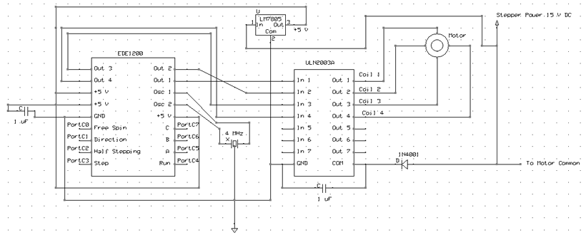 (Click to Enlarge) A schematic of our 5 V step motor circuit.
Digital Stimuli Toggling Circuit
Our system allows the use of 4 extra pins to be toggled for stimuli application. Ports B0 – B3 are connected to the ULN2003A with a 12V common power input. These pins can be used to control odor pumps, or other stimuli / data collection equipment. The power supply is stepped down from the 15V power supply using a 12V voltage regulator (LM7812). This component could be changed to fit in the power requirements of different desired hardware.
Sensor Hardware
We use an IR emitter-detector pair for each motor to detect when the motors are in the correct position. In our microcontroller, port D2 (feeding station sensor) and port D3 (magazine station sensor) were set as input pins to trigger an ISR. We found it necessary to use the LM358 op amp to make a digital switch from our sensors, similar to the lab 4 fan speed circuit. When we tried to make the circuit without the op amp, the ISR was triggered unpredictably. Sometimes the motors would skip stop position completely. Other times, when the motor was resumed from the stop position, it would immediately stop before reaching the next stop position.
Other hardware
In the actual apparatus, the motors, and the ISR sensors are connected to a 25 pin DSUB connector for ease of connectivity to our circuit. The pinouts are shown in the appendix.
Software Design
The software on the microcontroller is contained in serialcontrol.c. This can be found in the appendix below. The functionality of the code can be broken up into three main sections. These include receiving commands from the Matlab program through a serial connection and parsing the commands, calling the corresponding functions in the code, and controlling interrupt service routines for the sensors.
Parts List:
| Part Description | Part # | Cost |
|---|---|---|
| Step motor controller x2 | EDE1200 | $6 |
| Motor Driver x3 | ULN2003A | $2 |
| NAND gate | 7404 | $.50 |
| Inverter | 7402 | $.50 |
| 4 Mhz Crystal x2 | CTX080-ND | $1.0 |
| Mega644+ PCB+ external components | NA | $30 |
| Diode | 1N4004 | $0.27 |
| 5V regulator | LM7805 | $0.43 |
| 12V regulator | LM7812 | $0.43 |
| Serial cable | NA | $5 |
| Firewire cable | NA | $10 |
| Video camera | NA | $150 |
| Step motor x 2 | In possession | $50 |
| Plexi-glass scrap | NA | $50 |
| IR sensor emitter pair x 2 | LTE4208/LTR4206 | $1.50 |
| Gear and Rack pair | 2 of part# 6325k94 1 of part# 6295k243 |
$50 |
| 1″x.125″ steel dowels pins x14 | NA | $2 |
| 450 Ohm resistors | NA | $0.50 |
| 10uf capacitors | NA | $0.50 |
| Microscope with Camera Lens | NA | NA |
For more detail: Automated Pavlovian Classical Conditioning of Insects Using Atmega644