Summary of Autonomous Car
Summary: The project is an optical line-following autonomous vehicle using reflective phototransistors and an Atmel 8515 microcontroller. It corrects small deviations by steering and large deviations by backing up while steering to re-center. Speed control is mechanically managed. Hardware was wire-wrapped rather than breadboarded; drive is rear-wheel with differential via a DC motor and steering via a solenoid. Two H-bridges built from TIP-31, TIP3055, and TIP-42 BJTs provide power; 20-gauge wire used for high-current paths.
Parts used in the Line-Following Autonomous Car:
- Reflective phototransistors
- Atmel 8515 microcontroller
- DC drive motor (rear-wheel drive with differential)
- Steering solenoid
- TIP-31 BJTs
- TIP3055 BJTs
- TIP-42 BJTs
- Wire-wrap wiring
- 20-gauge wire (for high-current areas)
- 30-gauge wire (for remainder of circuit)
- CMOS logic supporting the H-bridges
Introduction
Our vehicle uses optical sensors to follow a line on the floor. Some autonomous vehicles used in manufacturing use a similar concept. Following magnetic strips embedded in the factory floor. The versatility of an optical design should be readily apparent. Since re-routing the vehicle requires no more than re-painting a line.
High-Level Design
Our vehicle uses reflective phototransistors to follow a line on the ground beneath it. The state of the phototransistors is captured, and the car is controlled accordingly by an Atmel 8515 microcontroller. If the car detects a small deviation from the line, it will correct its path by steering in the appropriate direction. If it detects a large deviation, it will take more “drastic” measures to correct its path: It will back up while steering itself back towards the line until it re-centers itself. It then continues on its path.
The original objective for this project was to optimize the car for the speed with which it navigated the line. To do this, we would have increased the speed when little compensation was needed, and decreased the speed as more was needed. This optimization, however, did not require much more effort on our part than the heuristic outlined above. This is because the speed is mechanically regulated by the gradual acceleration of the car in balance with the direction reversal for large corrections.
Hardware
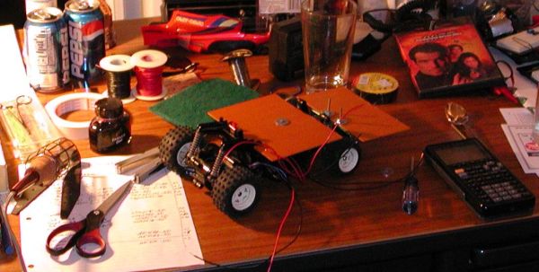
The hardware for this project was the bulk of the work. Because we were making a moving vehicle, we decided that it would be best not to have any of the circuitry on breadboards. Breadboards are also expensive, so we probably would have had to disassemble the car after its demonstration. We therefore chose to wire-wrap all of the circuitry. This required a fair amount of labor, but it was well worth it in the end.
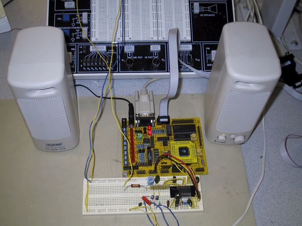
The car we selected is fairly simple to operate. It has a rear wheel drive, complete with a differential, which is powered by a DC motor. The steering is not controlled by a servo, but rather by a solenoid. This results in an “all or nothing” control over the steering, but we did not find this to be overly constraining. We built two H-bridges using TIP-31, TIP3055, and TIP-42 BJTs to deliver power to the steering and the drive motor. Because of the current requirements (the drive motor and steering solenoid could draw several amps), we used 20-gauge wire for the high-current areas of the H-bridges rather than the 30-gauge wire used for the rest of the circuit. Schematics of the H-bridges and supporting CMOS logic appear below.
For more detail: Autonomous Car
- What sensor type does the vehicle use to follow the line?
The vehicle uses reflective phototransistors to follow a line on the ground beneath it. - What microcontroller captures the phototransistor state?
An Atmel 8515 microcontroller captures the state of the phototransistors and controls the car. - How does the car correct small deviations from the line?
It corrects small deviations by steering in the appropriate direction. - How does the car handle large deviations from the line?
For large deviations it backs up while steering toward the line until it re-centers, then continues. - What components are used to build the H-bridges?
The H-bridges are built using TIP-31, TIP3055, and TIP-42 BJTs. - Why was wire-wrap used instead of breadboards?
Wire-wrap was used to avoid breadboards on a moving vehicle and to prevent having to disassemble the car after demonstration. - What gauge wire is used for high-current areas?
20-gauge wire is used for the high-current areas of the H-bridges. - How is steering implemented on the car?
Steering is implemented with a solenoid, providing all-or-nothing control rather than a servo. - Did the project implement speed optimization based on deviation?
The original objective included speed optimization based on needed compensation, but mechanical regulation of acceleration and direction reversal achieved the behavior with minimal extra effort.