Summary of AVR Microcontroller based Temperature Monitoring and Control System
AVR-based temperature controller using an LM35 sensor and Atmega8 MCU to measure temperature and a 16x2 LCD to display set point, heater status, and current temperature. A 12V relay (driven via BC548 transistor) switches the heater on/off. Two tactile switches adjust the set point. Circuit diagram, PCB layout, component placement, Proteus simulation, and code are provided for building or simulating the project, suitable for applications like an automatic temperature-controlled soldering station.
Parts used in the AVR Microcontroller based Temperature Controller:
- Atmega8 Microcontroller
- LM35 Temperature Sensor
- 12V Relay
- 16x2 LCD
- BC548 Transistor
- 1K Ohm Resistors
- Tactile Switches (2)
AVR Microcontroller based Temperature Controller, it uses LM35 Temperature Sensor for measurement of temperature and 16×2 LCD is used to display temperature set point, Heater Status and current temperature, It controls temperature by turning on and off of the heater using relay.
This project is very useful for controlling of temperature, It can be used for soldering station to make it automatic temperature controlled.
In this project two switches are used for setting the set points. You can try this project using Protius simulation. Circuit diagram, Layout is provided with code. Download respective files.
Simulation Results: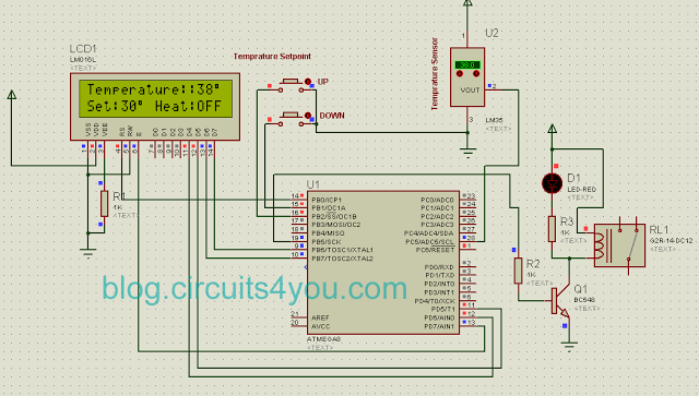
Step 1: Components Required
1. Atmega 8 Microcontroller
2. LM35 Temprature Sensor
3. 12V Relay
4. 16×2 LCD
5. BC548
6. 1K Ohm Resistors
7. Tectile Switches
Step 2: Circuit Design and PCB Manufacturing
Download Requires Files
1. Try Simulation Click Here to Download Protius Simulation File
2. Download pdf Complete Circuit Diagram
3. Download pdf PCB Layout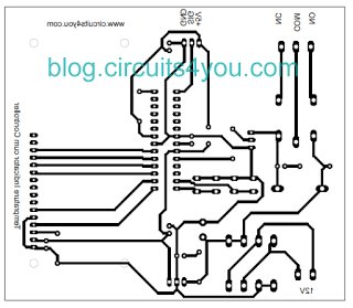
4. Download pdf Component Placement Diagram
5. Assemble components using above files.
For more Detail: AVR Microcontroller based Temperature Monitoring and Control System
- What microcontroller is used in the project?
The project uses an Atmega8 microcontroller. - How is temperature measured in the system?
Temperature is measured using an LM35 temperature sensor. - How does the controller switch the heater on and off?
The controller drives a 12V relay (via a BC548 transistor) to turn the heater on and off. - How is the temperature information displayed?
A 16x2 LCD displays the temperature set point, heater status, and current temperature. - How are set points adjusted?
Two tactile switches are used to set and adjust the temperature set points. - Are files available to simulate and build the circuit?
Yes, Proteus simulation file, circuit diagram PDF, PCB layout PDF, and component placement PDF are provided for download. - Can this project be used for a soldering station?
Yes, the project notes it can be used to make a soldering station automatic temperature controlled. - What components are used to drive the relay?
A BC548 transistor and 1K ohm resistors are used in the relay drive circuit.