Summary of AVR Switch Timer using ATmega8 Microcontroller
The project describes a Switch Timer designed by Andrianakis to improve UV exposure accuracy. It uses an ATmega8 microcontroller paired with two 7-segment LED displays to show the time. Users set and start the timer with two buttons. When the timer ends, a relay is switched off and a buzzer sounds. Timing accuracy is enhanced by a 32.768 KHz RTC crystal used with timer interrupts, and the firmware is written in C, compilable with WinAVR.
Parts used in the Switch Timer:
- ATmega8 microcontroller
- Two 7-segment LED displays
- Two push buttons (for set and start)
- Relay
- Buzzer
- 32.768 KHz RTC crystal
To get better UV expose, Andrianakis has built new Switch Timer that will turn of his UV exposure box after some time. The timer uses ATmega8 as main processor and two 7-segments LED as display. There are two buttons for set and start the timer. When time runs out, microcontroller switches relay and also sounds a buzzer.
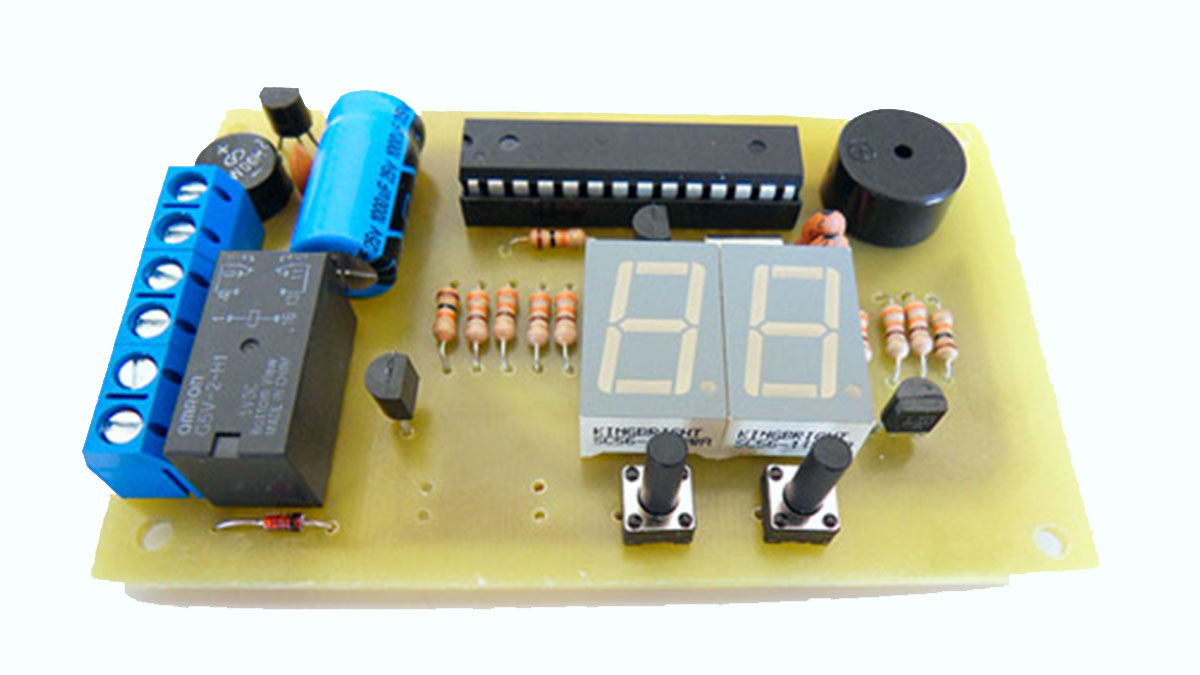
The time is calculated by timer interrupt triggering using a 32.768 KHz RTC Crystal with better accuracy. The firmware is written in C and you can compile it using WinAVR.
For more detail: AVR Switch Timer using ATmega8 Microcontroller