Summary of BalanceBot Using Atmega644
The BalanceBot is a low-cost, single-axis self-balancing robot designed as a proof of concept using an ATMega644 microcontroller and a PID control loop. It utilizes recycled materials like soda bottles and chopsticks to minimize expenses while demonstrating stabilization capabilities despite using a low-precision accelerometer. The system adjusts its center of gravity via a servo-driven head to maintain equilibrium on a singular axis.
Parts used in the BalanceBot:
- Mega 644 Microcontroller
- Custom PC Board
- DIP socket
- Servo Motor (Tower Hobbies TS-53)
- Accelerometer (MMA1260D)
- 9V Batteries (2 units)
- Mountain Dew Soda Bottle
- Chopstick
- Pennies (3 units)
- Bamboo Stick
- Popsicle Sticks
- Starbucks Glass Bottle
- 9V clip and regulator
- LM340LAZ-5.0 regulator
Introduction
The BalanceBot is a singular axis self balancing robot that is capable of adjusting itself to changes in weight and position. We developed the Balance Bot (BB or B2) from a single servo and a single accelerometer. This was very much a proof of concept to show the capabilities of the ATMega644 in doing PID loops even with limited accuracy in position readings. The parts and cost for this project were kept to a minimum. We wanted to create an inexpensive dynamic robot that utilized recycled parts. It should be easily reproducible given the right parts and code.
High Level Design
Several applications call for stabilization and balancing such as in flight, cameras, segways, etc. Some skyscrapers utilize stabilization/balancing to safeguard against heavy winds, storms, and earthquakes.
Now, consider one of the most known balancing acts, tightrope walking. What does it take for a tightrope walker to keep balance? Balancing involves two major components: Equilibrioception (sense of balance) and a means to change your center of gravity to get back into balance. In the case of a tightrope walker, equilibrioception is determined from fluids in the inner ear and his arms or a balance stick is used to adjusting the center of balance.
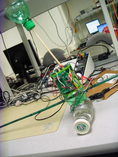
The tightrope walker was our inspiration for the design of the B2. As in the figure 1, the B2 has a stabilization stick, a balancing head for shifting its center of gravity and an MCU with accelerometer input for equilibrioception.
In designing the B2 we decided that we would utilize a very cost-efficient design in lieu of any expensive parts that might offset our budget. Because of this decision we ended up sticking with one MMA1260D that was sampled from Freescale. This accelerometer lacks high precision or accuracy, and made the programming process more difficult.
The best option for a robot of this design would be a gyroscope, but they are expensive and would make reproducing this robot quite pricey. With the accelerometer we were able to get quick output with very little conversion or set up. In the design phase these also helped because we accidently reverse charged one and blew it out. Replacing the accelerometer was very quick.
With the software we tried to avoid using too much complex math as it would slow down the reaction time between the MCU and the servo. Thus, we were not able to use any complex equations in our code design, though we did implement a PID controller.
Our design was not based on any standards and thus might not adhere strictly to any IEEE, ISO, ANSI, DIN, or other standards.
One big invention comes to mind when thinking of balancing, and that is the Segway PT. However, this product utilizes computers, tilt sensors and gyroscopes instead of accelerometers and microcontrollers. Thus, it is very different in design to the B2.
Concept : PID (proportional-integral-derivative)
We decided to tackle the challenge of balancing using PID control, a control feedback mechanism used for systems that need to self correct errors. In our case, our error is any acceleration. Since the axis of our accelerometer is parallel to the ground when balanced. If the robot is tilted, gravity will register as acceleration. Our accelerometer does read acceleration do to the movement of the robot balancing head, however correcting this acceleration will keep the robot from moving too wildly. Consider the following PID equation:
In our case, PID is the amount of swing the robot will move his balancing *head to fix the error. What each term does is as follows:
- A⋅ Error : This term is exactly proportional to the error. If the robot is tilted one way, it would compensate and swing its *head other way proportional to the error. This term is direct reaction to the accelerometer. The coefficient A cant be too large or else the balancing becomes a positive feedback loop.
- B⋅ Integral : This term is proportional to the integral of errors over time. This fixes any accumulating error that builds up if the first term hasnt already corrected it. Since the integral is an accumulation of past errors, the coefficient B cant be too large or else the robot will keep on adjusting for past errors even if the robot finally corrects itself (aka overshooting).
- C⋅ Derivative : This term is proportional to the derivative of error. This term is used to predict future error and adjusting the arm accordingly to prevent that error. This is very important since our sampling and reaction is discrete; the robot cant continuously react between intervals and thus must start adjusting to where it thinks the error will be. The danger of too big of the coefficient C is that the derivative is extremely sensitive to noise. Reacting to such noise can lead to erroneous adjustments.
*See below for hardware explanations.
Hardware/Program Design
Hardware
In terms of hardware we decided to keep the parts to a minimum and utilize recycled materials as much as possible. The main components of the B2 consist of the MCU and evaluation board, accelerometer, servo motor and two 9V batteries with voltage regulators. The chassis is made of a Mountain Dew (though we are not being sponsored in any way by Pepsi Co) bottle and the head consists of a chopstick with the top third of the bottle mounted to the top. The bottom of the chassis is stabilized by wide popsicle sticks. Refer to the parts list for details.
The body of the B2 is assembled with the servo mounted to the top back of the body, the MCU board on the inside left middle wall, one 9V battery underneath the servo, one 9V battery on a regulator board on the front outside middle wall and the accelerometer mounted to the rotational object below the B2 (in this case a glass Frappuccino bottle). This can be seen in the pictures of the B2. Because of accuracy issues that came from acceleration other than gravity we deemed it best to move the accelerometer to the base of the B2 instead of on the main body.
Our original plan for keeping equilibrium was to have a horizontal beam that would shift from side to side to adjust for weight, but for ease of setup we went with a moving head design instead. The head of the B2 extends about a foot off the body and is attached via the servo motor. The top of the head is open to allow for weights to be added or removed easily during the calibration process. The head swings with the servo, and therefore must be light enough for the servo to move at all times.
One 9V battery is attached to a Freescale voltage regulator board that allows for the 9V battery to be split into 3V and 5V outputs. We use the 5V output to drive the accelerometer. This 9V battery is also connected directly to the MCU board to power the MCU with 9V. The other 9V battery is attached to a LM340 5V voltage regulator that drives the servo.
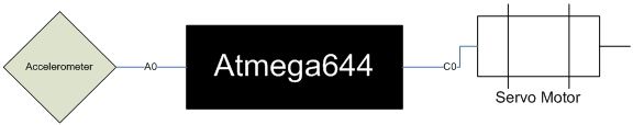
The accelerometer is attached to Port A0 on the MCU and the servo output comes from Port C0. All of the grounds for each element in the B2 are tied together to form a common ground.
At first all the parts were mounted to a soda can, but the coating on the can scraped off at the solder points for the various components causing them to short. Thus we switched to a larger and more durable plastic bottle.
Software
ADC
The B2 uses only one input to determine how much correction it should do. This input is from the ADC from Port A0. The ADC is initialized as follows:
ADMUX = (0<<REFS1)|(1<<REFS0)|(1<<ADLAR);
ADCSRA = (1<<ADEN) | (1<<ADSC)+ 7
By default ADMUX selects channel 0 if no channel is specified in the ADMUX register. Setting REFS1 to 0 and REFS0 to 1 turns on the 5V internal referencing, and setting ADLAR to 1 tells the MCU to use only the top 8 bits for readings as the lower 2 bits are inaccurate.
The ADCSRA register controls the state of the ADC. Setting ADEN to 1 turns on the ADC, and setting ADSC to 1 starts the first conversion. When the conversion is complete ADSC becomes 0 again. Therefore in task2 we perform the operation ADCSRA |= (1<<ADSC) to start new conversions.
Adding 7 to ADCSRA sets the prescalar to 128 which means the frequency is divided by 128. We chose this frequency because it does slower conversions, thus increasing accuracy, while still sampling faster than task2 checks for new values from the accelerometer.
The converted value is stored in the ADCH register, which we store in Ain. The first conversion done is a dummy because the first conversion does not give a meaningful result. We then take the first true conversion and define the centerof the B2 as this value. Thus, resetting the B2 allows the user to define a new center each time. This comes in useful when the user wants the B2 to balance at a position not in the direct center.
Parts List:
| Part | (Brand) | Vendor Cost |
|---|---|---|
| Mega 644 Microcontroller | Sampled from Atmel Representative | $0.00 |
| Custom PC Board | Bruce | $4.00 |
| DIP socket | Bruce | $0.50 |
| Std Servo Motor (Tower Hobbies TS-53) | Bought from a friend | $9.99 |
| Accelerometer (MMA1260D) | Sampled from Freescale acquired from Bruce | $0.00 |
| 2 batteries (9V) | Dollar Store | $1.00 |
| Soda Bottle (Mountain Dew) | Recycled | $0.00 |
| Chopstick | Matin Caf� | $0.00 |
| 3 Pennies | Change jar | $0.03 |
| Bamboo Stick | Dollar Store | $0.15 |
| Popsicle Sticks | Matin Caf� | $0.00 |
| Starbucks Glass Bottle | Recycled | $0.00 |
| 9V clip and regulator | Sampled from Freescale acquired from Bruce | $0.00 |
| LM340LAZ-5.0 regulator | Bruce | $0.00 |
| TOTAL | $15.72 |
For more detail: BalanceBot Using Atmega32
- How does the BalanceBot achieve stability?
The robot uses a PID control loop where the error is acceleration detected by an accelerometer parallel to the ground. - Why was an accelerometer chosen over a gyroscope?
Gyroscopes are expensive and would make reproducing the robot pricey, whereas the accelerometer provided quick output with minimal setup. - What inspired the design of the B2?
The design was inspired by tightrope walking, utilizing a stabilization stick and a balancing head to shift the center of gravity. - Can the user redefine the balance position?
Yes, resetting the B2 allows the user to define a new center based on the first true conversion value from the ADC. - What material was used for the chassis instead of a soda can?
A larger plastic Mountain Dew bottle was used because the coating on a soda can scraped off at solder points causing shorts. - How is the voltage regulated for the components?
One 9V battery powers the MCU directly and feeds a regulator for the accelerometer, while another battery drives a separate regulator for the servo. - What is the function of the derivative term in the PID equation?
The derivative term predicts future error to prevent it, which is crucial since the robot cannot react continuously between sampling intervals. - Where is the accelerometer mounted on the robot?
The accelerometer is mounted to the rotational object below the B2, specifically a glass Frappuccino bottle, rather than the main body.