Summary of Battle video game Using Atmega644
This project implements a two-player tank battle game inspired by "Battle City," using three microcontrollers to handle game logic, video output, and audio. The main CPU manages player inputs via keypads and coordinates with separate video and audio controllers to overcome memory and processing limitations. The system features a 16x16 grid map where players destroy walls and each other using missiles, with graphics rendered on a black-and-white TV following the NTSC standard.
Parts used in the Tank Battle Game:
- Mega644 Microcontroller (Main CPU)
- Video Controller Microcontroller
- Audio Controller Microcontroller
- Two Keyboards/Key Pads
- Black-and-White TV
- 8-bit Bus Connections
- 1K Ohm Resistors
- Timer 0 Interrupt System
Introduction
Our project is a simple game where two players control tanks in a stage with the ultimate goal of destroying each other. User input is achieved through the use of keypads, which are used to both control the tanks and fire missiles at one another.

The reason that this project was chosen was because it effectively combined most of the things we learned in this class. In addition, we all enjoy video games, and were curious if it was possible to construct an entire video game system using a microcontrollers, instead of simply the software side.
We picked this game because we wanted the demo to have more user interactions. This game allows two players to fight against each other rather than only one player playing. The game is inspired by the Nintendo “Battle City” game. We programmed this game for educational purpose only, so it is considered a fair use.
High Level Design
The game we have implemented is a simple adversarial game where two players control tanks in a stage and attempt to shoot each other. Terrain is in the form of walls, which are destroyed by missiles fired by tanks. User input is implemented through the use of two keypads, which are read through polling and the use of a debounce state machine, adapted from code provided in earlier labs.
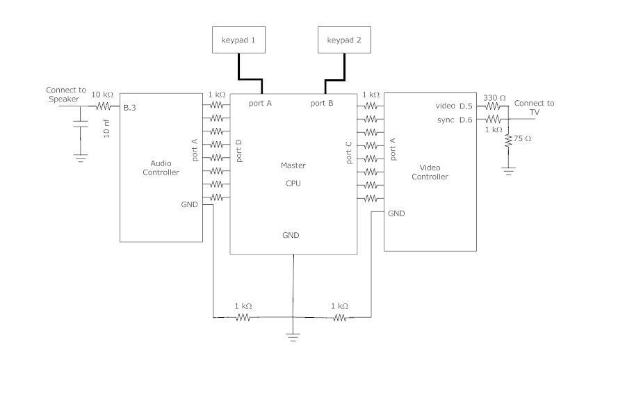
Because the Mega644 has very limited memory and frequency. We decided to move the video control and audio control out of the main processor. As we have studied, the audio controller may take more than 75% of the CPU (at 16MHz) time and 50% of the memory, and the video controller will take over 75% of CPU time and 90% of the memory. Therefore, the audio and video controller are built separately.
By having more CPUs, we have more communication overhead. The main CPU communicates with the audio controller and video controller using an 8-bit bus for each, and the ground of these three units are shared. Note that between the connection of each port, there is a 1K ohm resistor between each connection pin. This is to protect spikes from a unit when another unit turns on.
The video controller runs at 16 MHz and refresh the TV screen at 60 Hz. The resolution is 192×150. It generates a video signal and sync signal and outputs to the black-and-white TV. It’s able to update the game sprites based on the commands from the main CPU. The TV output is based on the NTSC standard.
The audio controller controls the game song and sound effect. It implements FM (frequency modulation) for the songs and DPCM (differential, pulse-code modulation) for the sound effect and the sampling frequency is 8kHz. It’s able to play different music and sound based on the commands from the main CPU. It runs at 20MHz because we think this will give the CPU more speed to handle more audio synthesis.
Some of the video code is adapted from a previous group’s final project, while sound code is adapted from code used in lab3 for additive synthesis, along with matlab code taken from the course website to convert sound effects into something our sound processor can use. The game music is coded from some existing pieces of music. Since this project is only for educational purposes and we only took a small portion of the music, it is considered a fair use.
The connection of the keypad is demonstrated in lab2: http://people.ece.cornell.edu/land/courses/ece4760/labs/s2012/lab2.html
Program Design
Game Design
On a high level, the code is composed of 3 separate tasks, along with a very simple interrupt vector. Each of the 3 tasks controls a specific fucntion of the game, and the interrupt vector is simply used as a very simple scheduler in order to run each task at a certain frequency. Task1 is responsible for tracking all missiles that are in flight, along with queueing graphical and sound updates related to missile updates. Task2 handles user i/o, and consists of two debounce state machines for each player. Task3 dequeues elements of the graphical and sound buffers at a speed that our sound and graphics microprocessors can handle, and as such is also responsible for controlling communication between our 3 microprocessors.
Because of the persistent nature of player controlled tanks and missiles, both missiles and tanks were defined as structs in order to reliably keep track of their state. All missiles in flight are stored in an array that is iterated through by task1 in order to control movement and collisions with other objects. In addition, the current state of the playing field is maintained in an array, with the value of each element corresponding to the object at that position.
Interrupt Vector:
Timer 0 is set to trigger an interrupt every millisecond. When triggered, the interrupt vector simply decrements 3 counter variables, which are used to keep track of when each of the three tasks are run. This behavior is derived from the interrupt behavior of previous labs in the ECE4760 class.
Important data structures:
missile_t is a data structure used to keep track of position and direction of missiles.
p1_missiles, p2_missiles are arrays of missile_t types that are used to organize all existing missiles, along with simplifying iteration through all missiles for graphical and game updates.
tank_t is a data structure used to keep track of position and direction of each tank, with 2 initializations of player_1 and player_2.
char map[16][16] is an array that maintains the state of the entire game stage, including positions of missiles, walls, and players.
framebuffer, soundbuffer are arrays used as rotating buffers in order to keep track of and maintain commands that will be sent to the sound or graphics processors.
Functions:
initialize_system():
Initialize_system initializes all necessary state variables (data structures, queue pointers, etc.) alon with setting all ports to the correct output direction. In addition, it also sets timer 0 to trigger an interrupt every 1 ms for the purpose of scheduling tasks.
initialize_stage():
Initialize_stage initializes the map used to keep track of game state, along with initializing the data structures that keep track of all missiles in flight.
task1():
Task 1 is run 16 times a second, and is responsible for controlling all missiles currently in flight. It iterates through the missile arrays, finding all valid missiles, and then advances them one step, triggering different actions based on the contents of the contents of their new position. If there is a wall, then the missile and wall are both destroyed. If there is another missile, both missiles are destroyed. In the case of an empty space, the missile is simply moved to the new space, and if the space is the enemy player, then the player who fired the missile wins the game. This process is repeated for the missiles of both players, with changes to state as appropriate.
task2():
Task 2 is responsible for debouncing the user inputs through keypads, and is run 40 times a second. The debounce logic is virtually identical to the example code given by Bruce Land for lab1 of this class. If there is a successful button press, then the buttonpressed() function is called, which is responsible for interpreting the user input.
task3():
Task3 is responsible for dequeing graphical and sound updates off of their respective buffers, and runs 250 times a second. It essentially drives the bus used to communicate with the sound and graphics processing microprocessors, along with incrementing head pointer of the rotating buffer.
Main:
The Main function simply keeps counters for each task and calls the respective task function when appropriate.
Video Controller
The video controller is adapted from the video generation code from ECE4760 website: http://people.ece.cornell.edu/land/courses/ece4760/video/index.html
We modified the original code so as the game CPU is able to control the video more easily.
The video controller runs at 16 MHz and refresh the TV screen at 60 Hz. It generates a video signal and sync signal and outputs to the black-and-white TV.
The horizontal resolution of the video is 192 pixels, and the vertical resolution is 150 pixels. But we only use 192×130 of the screen. The game map, which is 128×128, located on the left size of the screen and an information bar is on the right side.
The main game map is further divided into a 16×16 grid, and each grid takes 8×8 pixels. The objects of the game, such as tanks, walls and bullets are located in each grid. The graphics of these objects, also known as sprites, are stored as 8×8 matrices in the memory, (as an array called objectbitmap). We define a function: void draw_object(char x, char y, char c), which will draw sprite c on the coordinate x, y of the grid from the pre-stored 8×8 matrix. Note that, the grids are represented by a 16×16 metrix, so each grid can have an 8-bit x(row) and y(coordinate) coordinate (x,y).
Sprites
Tanks: There are two tanks in the game, and their coordinates as in the grid are stored as variables. Tank 1 is the white one, and tank 2 is the black one. Note that each tank has 4 sprites, representing the up, down, left and right position, respectively.
Walls: The walls are black blocks. They are drawn during the initialization, and can only been clear when shot by the bullet during the game.
Bullet: A black round ball that goes straight.
None: An empty grid which is used to clear the object on that grid.
Initialization Function
During the initialization, the information bar is drawn, with the game name “Battle City” and legends for the tank.
Then, the game map is drawn. We put either “wall” or “none” in each grid. The user can hardcode the initial game map he likes in the initialization.
Finally, the two tanks are drawn. The default locations are tank 1 at (0,0) (top left corner) and tank 2 at (15,15) (bottom right corner).
Communication
When the game starts, the graphic is updated when the video controller receives commands from the main CPU.
Because of the hardware limitation, the communication link between the CPU and video controller is only 8-bit. We define our 8-bit communication protocol as the following (from MSB to LSB):
010abbbb: Update the coordinate of tank 1. If a==0, update the x-coordinate of tank 1 as bbbb; if a==1, update the y-coordinate of tank 1 as bbbb. Each update will redraw the tank’s position on the map if the tank is moved. The orientation of the tank is automatically calculated based on the last position.
011abbbb: Update the coordinate of tank 2. If a==0, update the x-coordinate of tank 2 as bbbb; if a==1, update the y-coordinate of tank 2 as bbbb. Each update will redraw the tank’s position on the map if the tank is moved. The orientation of the tank is automatically calculated based on the last position.
001abbbb: This command sets the grid to clear. The coordinate of the grid to clear is saved in a pair of variables (nonex, noney). If a==0, the x-coordinate of the grid to clear, “nonex” is set as bbbb; if a==1, the y-coordinate of the grid to clear, “noney” is set as bbbb, and the grid at (nonex, noney) is cleared .Because we can only send 8-bit at a time, to clear a grid, the main CPU needs to send two bytes of commands. The first byte tells the x coordinate, and the second byte tells the y coordinate and the grid is cleared.
100abbbb: This command sets the bullet to draw. The coordinate of the bullet is saved in a pair of variables (shotx, shoty). If a==0, the x-coordinate of the bullet to draw, “shotx” is set as bbbb; if a==1, the y-coordinate of the bullet to draw, “shoty” is set as bbbb, and the bullet at (shotx,shoty) is drawn. Because we can can only send 8-bit at a time, to draw a bullet, the main CPU needs to send two bytes of commands. The first byte tells the x coordinate of the bullet, and the second byte tells the y coordinate and the bullet is drawn.
111xxxxx: System commands. When
xxxxx == 0: game restarts. This will call the initialization function and reinitialize the whole game map and the information bar. SInce redrawing the game map takes a long time (note that only at most 500 points can be updated in 1/60s), we disable the interrupt and enable it after the update is done. This can be seen as a blink on the screen.
xxxxx == 1: Player 1 wins. The message “P1 wins” will be displayed on the information bar.
xxxxx == 2: Player 2 wins. The message “P2 wins” will be displayed on the information bar. “P1 wins” and “P2 wins” commands will be sent by the main CPU when the game is over.
For more detail: Battle video game Using Atmega644
- Why were video and audio controls moved out of the main processor?
The Mega644 has limited memory and frequency, as audio and video tasks would consume over 75% of CPU time and significant memory if handled by the main unit. - How is user input processed for the tanks?
User input is achieved through polling two keypads using debounce state machines to interpret button presses for movement and firing. - What resolution does the video controller use for the screen?
The video controller runs at 16 MHz with a resolution of 192x150 pixels, though only 192x130 is utilized for the game map and information bar. - How are walls destroyed in the game?
Walls are destroyed when missiles fired by tanks collide with them, causing both the missile and the wall to be removed from the stage. - What communication protocol is used between the CPUs?
The main CPU communicates with the audio and video controllers using an 8-bit bus with shared ground and 1K ohm resistors on connection pins. - How often is Task 1 executed to manage missiles?
Task 1 runs 16 times per second to track missile positions, handle collisions, and queue graphical or sound updates. - What happens when a missile hits an enemy player?
If a missile hits the opposing player, the player who fired the missile wins the game immediately. - How is the game map structured visually?
The map is a 128x128 area divided into a 16x16 grid where each cell is 8x8 pixels containing sprites like tanks, walls, or bullets.