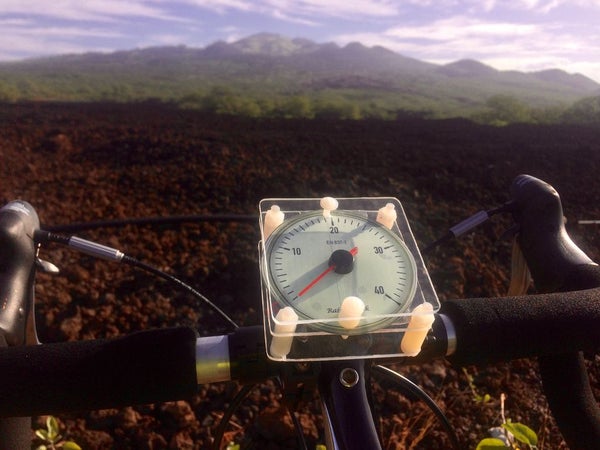
More patents for bicycle improvements have been issued than for any other machine. It is no wonder that the simplest of mechanical devices invites constant tinkering. If you do a search for speedometers for bikes you can come up with the old style mechanical contrivance with a gear driving a cable into a solid style housing that can still be bought on the web. While I have no great love for “retro” git I do like Analog as output rather than a number and my brain seems to like it better too. The instant picture of a state of being rather than the awkward pause of your brain circuitry going through translation hoops to get to a picture of time or speed. Anyway its rather neat to cruise down the street with a wizzy needle pointing out your lack of speed or short ride.
Using GPS is nice because it makes it self contained with no umbilical cord to the wheel. Its a little slow off the start –a second or two and it takes a minute or so to get its bearings right but if you are really OCD and must have a downloaded file of every inch that you traveled having a goofy dial on your bike is probably not for you. But for those who take some joy in the ride and want to fun-up their commute with their very own customized dial this may be a good project.
Step 1: Grab Some Hardware
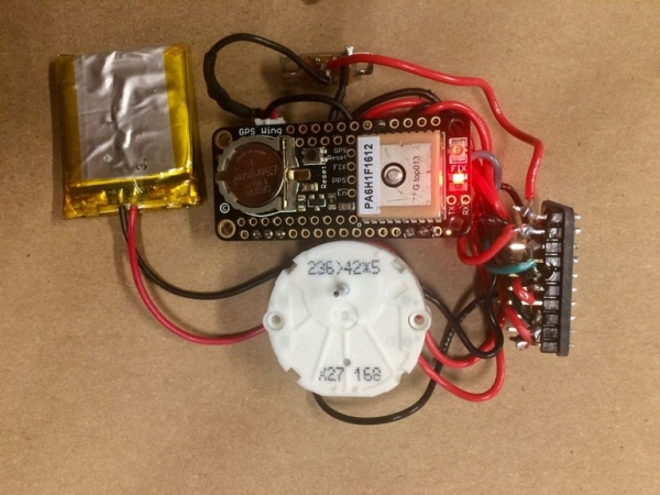
The Hardware is pretty simple. All of it can be ordered from Adafruit. You use one of their new Feather boards with a GPS Feather attached directly above it. The battery is a 500 mAh unit that provides about 6 hours of use in my testing. But you can fit whatever you want in the case. The Feather is nice because it has built in charging so when you take it off your bike you can flip it on the charger overnight. This is not something that your going to leave on your bike anyway–its too attractive. The stepper motor is one normally sourced for speedometers in cars and Adafruit has a nice one for reasonable cost with a needle but you can get piles of these for cheap on the web. The motor driver is necessary because GPS and steppers don’t play nicely together on these small computers. The plastic cases I ordered on the web work well for a solid weather tight enclosure but you can also just carve a stackable grouping out of raw plexiglass.
1. Adafruit Feather 32u4 Basic Proto
2. Adafruit Ultimate GPS FeatherWing
3. Lithium Ion Polymer Battery – 3.7v 500mAh
4. Breadboard-friendly SPDT Slide Switch
5. Adafruit TB6612 1.2A DC/Stepper Motor Driver Breakout Board
6. Automotive Gauge Stepper Motor – x27.168
7. Break-Resistant Plastic Drawer Organizers 3″ x 3″ x 2″ l Set of 12
8. Adafruit LED Sequins – Ruby Red, Green
Step 2: Wire It Up…
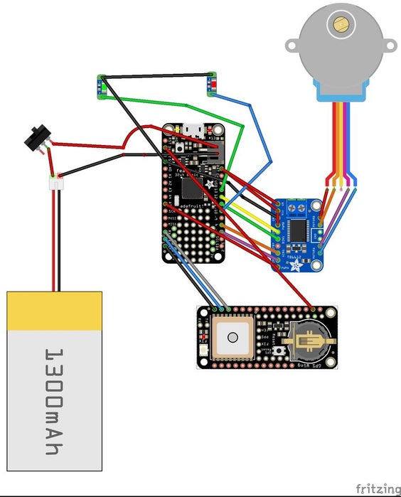
The usual–use a breadboard. Follow the instructions on the Adafruit web site for stacking the GPS Feather with the main protoboard and soldering the connections as noted. The hardware serial connects the TX of the GPS feather with the RX of the main Feather board and the RX of the GPS to the TX of the main board. These plus ground and power are the only connections this board needs with its mating partner. Its a wonderful idea to check that the GPS data and the main board are working correctly and transmitting parsed data so use the demos on the Adafruit web page to make sure these guys are up and running. Once you have seen the miracle of data streaming from these units–something we now take for granted–wire up the motor shield and the stepper motor and test it with the motor shield demo tutorial just to make sure its working. I wired the stepper motor with the lipo-battery output fully expecting it not to work and thinking I would need a voltage booster, but it works fine surprisingly. Be very careful of the tiny solder pins on the stepper motor–they are really fragile and break off just where they come out of the case so as soon as you solder them to wires add some hot glue to the wire to stop any tension from torquing the connections. The switch in the diagram is for On/Off of the unit and the LED sequins are for various software defined uses.
Step 3: Enclose It
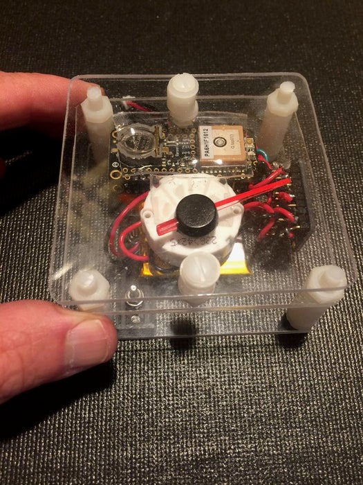
I built several different enclosures for the speedometer. The first was just a series of stacked cut plexiglass sheets with nylon spacers. The components were held on to the plates with double sided clear tape. It worked well for Maui where it doesn’t rain much but for Alaska I needed a more substantial plexiglass box. The components were held on to a carefully seated plate that mated nicely with the constriction 2/3 into the box providing a protected area for the needle to move in. Make sure you create an opening for the charging/programming cable to the computer. The GPS unit should be positioned so it has a good view of the sky.
Step 4: Your Dial
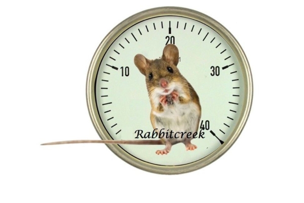
The stepper is not really a stepper but goes around 300 degrees. There are 600 steps in this range and you have to design your dial accordingly. The GPS puts out Altitude, Speed and Distance and I programmed the unit to display any of these. The download software is currently configured to display speed in MPH when moving and distance in Miles when stopped–I hate nested button pushing….so the skies the limit in terms of what you want for output with a needle–for biking up Haleakala in Maui(10,000 feet elevation gain) change up your dial for an airplane altimeter dial. Say you have a bad boring commute with your favorite dog on one side of the dial and your pointy haired boss at the other–or if you have to do the middle earth commute from the Shire to Mordor every day. Anyway just do up whatever you want in photoshop or hand drawn in sand on the beach and send it off to the printer–it should be about 2.75 inches in size like your housings. I encased mine in packing tape for added protection and punch a nice size hole in the center for the needle bearing. The needle is funny–run the program and it will initialize the starting position and hold–then place the needle on the bearing to match up with zero or the shire or your dog. Push down firmly to get it to seat…its a little funky. To remove it use a fork to wedge it up. You may have to trim the needle to fit the enclosure box.
Step 5: Software
The software uses TinyGPS plus for the parsing of the GPS data. I used this because calculating distance is a very easy function in this Library. The comments in the software should help you figure out how to configure it to your needs. Currently the software starts by racking the stepper back and forth to its limits and then coming to a rest at zero on my dial–but your dial will be different so you may have to adjust. If you want to measure all distance from a fixed site just set it in homeLat and homeLng. The unit sits until it has a good fix and is parsing non-zero lat and long and sets these as your initial position. For distance it chews off 200 meters before it changes to the next lat/lng stacking up 200 meter bits in a straight line to gain your total distance. There is a commented out section in case you want to run the LED’s to tell how the battery is doing. (See Adafruits description of how this is done…). I use mode to control what output you want at the end of the loop section. Currently as it is set the Green LED sequin comes on when you are moving and the dial is displaying speed and the Red LED comes on when you stop and your total total distance is displayed.
Step 6: Using It
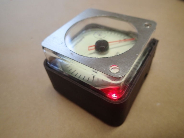
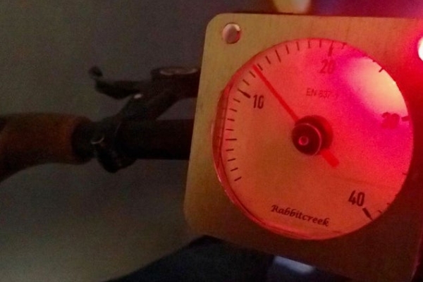
I dressed the plexiglass enclosure with some leather and Aluminum. Its easily mounted to your handlebars with a bike-light attachment holder. Or you can use one of those iPhone bike mounts that are so cheap now on the web. To charge just plug it in for a while(with switch on…battery has to be connected) When its mounted on your bike it will quickly sweep the limits of the dial and then stop until it gets a GPS fix–this is indicated by the slow blink of the GPS board. Peddling starts the speedometer and stopping brings up total distance. The LED’s will even light the dial for night commutes.
Source: Bike Analog Speedometer
