Summary of Binary DVM
This article details building a battery-powered Digital Volt Meter (DVM) using a Micro:bit that displays voltage in both decimal and binary formats. A potential divider network scales input voltages up to 20V down to the Micro:bit's safe 3V ADC limit. The project includes code to convert analog readings into voltage values, apply offset corrections, and render the results on the LED matrix as text or binary patterns triggered by buttons.
Parts used in the Binary DVM:
- MicroBit
- Battery Pack
- 9k resistor
- 953R resistor
- 200R multi turn potentiometer
- 1K resistor
- Veroboard
- Veropins
- Bread:bit Edge Connector Breakout Board
- LED red low current
- 16 pin DIL socket or SIL socket strip
- DMM
- PSU, fixed or variable voltage
- PP3, 9V non rechargeable battery
- 4 pin single in line SIP pin header
Binary displays are very popular for clocks so it looked like there a gap waiting to be filled in the measurement area with an instrument that displayed its results in a Binary format. As result I decided that a DVM would be a suitable project to be given a Binary makeover.
The Microbit has the means via an ADC (Analogue to Digital Converter), to convert analogue inputs into digital values. These digital values can then be used to create a myriad of applications.
In this case I will describing how to make a Battery powered Digital Volt Meter (DVM), but in addition to this I will have the ability to display the voltage in Binary as well as the usual Decimal values.
** NOTE ** ENSURE THAT ANY VOLTAGE DIRECTLY APPLIED TO THE MICROBIT DOES NOT EXCEED THE SUPPLY RAIL (~3V), AS YOU WILL DAMAGE THE MICROBIT
If you were to apply a DC input to the ADC this being limited by the supply would mean that ~3V would be the maximum.
However, there is a way to overcome this limitation with a few additional components to measure voltages greater than the supply without causing damage to the MicroBit.
It must be noted that there is a limitation to what this simple DVM will measure and its only intended for low voltage positive DC applications in this case 0 to 20V.
Supplies:
MicroBit – Qty 1
Battery Pack – Qty 1
9k resistor* – Qty 1
953R resistor* – Qty 1
200R multi turn potentiometer* – Qty 1
1K resistor* – Qty 4
*All resistors 0.1W or greater.
Veroboard – Qty 1
Veropins – Qty 3
Bread:bit Edge Connector Breakout Board – Qty 1 or similar to allow the Microbit to be connected to the potential divider.
LED red low current – Qty 2
16 pin DIL socket or SIL socket strip – Qty 1
DMM
PSU, fixed or variable voltage.
PP3, 9V non rechargeable battery.
In the absence of a PSU a battery as indicated may be substituted.
4 pin single in line (SIP), pin header – Qty 2
Step 1: Potential Divider
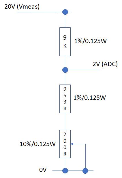
In order to enable a voltage greater than the supply to be applied to the ADC input we will be using a potential divider network.
This network will enable the application of a scaled voltage at the ADC input, this scaling will be accomplished using resistors.
The basic network is made up of two resistors which divides the applied voltage across each resistor.
If we adopt a scaling factor of 1/10th the input, at the ADC then for an applied voltage of 20V; the maximum voltage at the ADC input would be 2V which is well within the capability of the ADC with a safety margin of 1V.
If we create a resistor potential divider using 9K & 1K with 20V across the network the voltage across the 1K resistor will be 20 * (1k/10k) = 2V.
However, components have tolerance and even with 1% resistors the voltage could be between 1.96V and 2.04V
Therefore, in order to compensate for the +/-40 mV variance we can add some variable resistance into the network to adjust for component, voltage & temperature variation.
Using a 1% 9k resistor and a 1k trimming resistor best case typical of 10% [0k9 to 1k1], its resistance would be between 0R (0V) and 1k1 max (2.198V [8K91] or 2.159V [9K09]).
Values significantly less then the value to be compensated for in this case 2V are undesirable.
Therefore, if the 1k potentiometer is replaced with a 1% 931R (0k922 to 0k94), fixed resistor in series with a 10% 200R (180R to 220R) potentiometer. This gives a compensation range of 1.84V to 2.3V (-160mV to +300mV).
Therefore, to set an accurate maximum input at the ADC we set the maximum input to be measured and adjust the potentiometer to get an accurate output. Using a DMM in both cases to set the voltages.
In the absence of a DMM to measure the input voltage use a 9V primary non-rechargeable battery as the input to the potential divider and adjust the potentiometer for 1/10th the input voltage (900mV), once the assembly is complete.
Step 2: ADC (Analog to Digital Conversion)
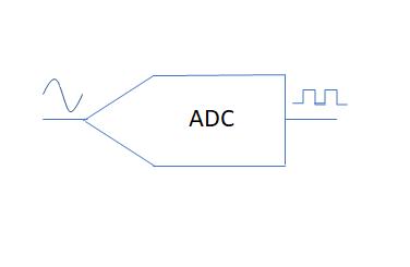
In order to convert the digital value that represents the input voltage into a value that can be displayed on the Microbit the following calculation is applied.
ADC 10 bit resolution = 0 to 1023 bits.
1 bit resolution = Vs/1023 = 3.226 mV, where Vs = 3.3V if powered by USB
If using a battery the voltage (Vs), will vary based on the type of battery and its state of health.
Therefore.
Volts = ADC value/1 bit resolution
100.006 mV= 31/3.3e-3
As the input has a 10:1 divider in the form of the resistor potential divider the resulting value is multiplied by 10.
100.006mV*10 = 1000.06mV (1.00006V) at the input of the potential divider.
This is coded in the Microbit within function Vconvert.
The ADC value is read into variable VIN.
Values >=0 are converted in to the equivalent voltage, VOUT
Vout = Vin * Vpbit * 10
But with zero volts at the input an offset error will exist which needs to be taken into account and included in the calculation.
The offset (Voff), can be found by connecting the ADC input to 0V
This value is then set to be stored in Voff.
The calculation then becomes:
Vout = Vin * Vpbit * 10 – Voff
Step 3: The Code
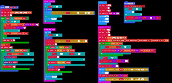
The Blocks code for the Binary/Decimal DVM
Step 4: Decimal Display
Having converted the digital value into a voltage, we now want to display this on the Microbit.
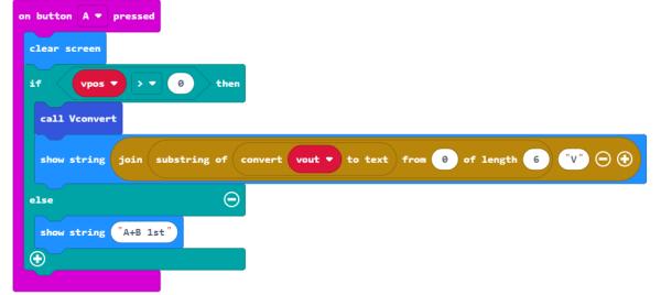
This is initiated by the On Button A pressed.
Vout is first converted to text.
A substring of the text containing 7 characters is created.
To this text is concatenated the letter ‘V’ for volts.
Show string is used to display the result.
This will scroll the result across the screen until all the has been displayed leaving a blank screen.
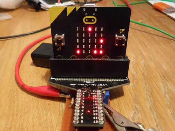
An example file is included with the same measurement displayed in both Decimal and Binary format.
The decimal value is 10.150V
Step 5: Binary Display
This is the part of the code that converts the Decimal value into its Binary equivalent.
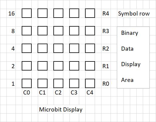
An explanation into the layout of the display will clarify how the data is arranged.
4 rows x 5 columns are used to display the numeric data with one column per decimal value. The column is arranged with the LSB on row 0 and the MSB on row 3 enabling a maximum Binary count of 15, but as this is representing a Decimal digit then the maximum value will be limited to 9. Row 4 the top row is assigned to symbols, these symbols being ‘-‘ (-ve) and ‘.’ (decimal point).
This process is initiated in the on button B pressed.
The result of Vconvert is converted to a text string of 5 characters and stored in STRVAL
A do while loop is executed for the character length of STRVAL
Each character is then split out in turn into STRMID
If STRMID is a number then this is converted into its Binary equivalent value, a non numeric value is given a default Decimal value of 16.
This process calls function DEC2BIN with two passing parameters, VALUE & INDEX3.
VALUE is the Decimal number to be converted and INDEX3 is the column number were the Binary value or Symbol will be placed.
An array LIST2 is defined with 5 elements, one element per column digit.
The process for converting the decimal value to its equivalent Binary value follows the form:
Take for example Decimal 6 to Binary.
6/2 = 3 r 0
3/2 = 1 r 1 = 011 (reverse) = 0110 (4 bits assigned per column)
The remainder from each division were the remaining integer is >1 is divided by 2 until no further integer division is possible. The remainder is stored in each element of LIST2 in the order calculated but this results in the MSB in element 0 and the LSB in element 3 which requires that the order in the values are reversed.
A do while loop is executed for the length of LIST2.
If the VALUE is >1 then it is divided by 2 and the remainder is stored in LIST2 at the index and VALUE becomes the integer, and the loop repeated else VALUE is stored in LIST2 at the index and the loop exited.
This process results in the Binary value being stored in LIST2 however, the elements are in reverse order and a Reverse LIST2 is executed to put each Binary bit in the correct order LSB at element 0.
Once the Binary value has been calculated it is displayed as a 4 bit word or nibble in the designated column. With one nibble per column up to a maximum of 5 columns. Symbols will be assigned to a 5th bit with all other bits=0 creating the following format 00001 or 00000. A one in the 5th bit indicating -ve or the decimal point and a zero indicating the absence of either of these symbols.
A designated column can only be assigned to a number or a symbol at any one time, numbers or symbols will not be mixed on the same column.
A do while loop is executed for the array length of LIST2
If the value in LIST2 at the element referenced by INDEX2 is one the LED in the reference column at the row referenced by INDEX2 is illuminated, if the value is zero the LED is un-plotted.
This will continue until each LED in the referenced column has been processed the result being either a number or a symbol.
The result will be retained on the screen between measurements.
Source: Binary DVM
- How can I measure voltages greater than 3V without damaging the Microbit?
Use a potential divider network with resistors to scale the input voltage down to within the supply rail limits. - What is the maximum voltage this simple DVM can measure?
The instrument is intended for low voltage positive DC applications ranging from 0 to 20V. - Why is a potentiometer included in the resistor potential divider?
It compensates for component tolerance, voltage, and temperature variations to ensure accurate scaling. - How does the code calculate the final voltage output?
The code reads the ADC value, multiplies it by the bit resolution and a factor of 10, then subtracts an offset error found at zero volts. - How are decimal digits converted to binary on the display?
The code divides the decimal number by 2 repeatedly to find remainders, stores them in reverse order, reverses the list, and maps them to the LED grid. - Which button initiates the decimal display?
Pressing Button A initiates the process to convert the voltage to text and scroll it across the screen. - Which button initiates the binary display?
Pressing Button B starts the process to convert the value into its binary equivalent and illuminate the LEDs. - Can I use a battery instead of a PSU if I do not have one?
Yes, a PP3 9V non-rechargeable battery can be substituted for the PSU to test the potential divider.