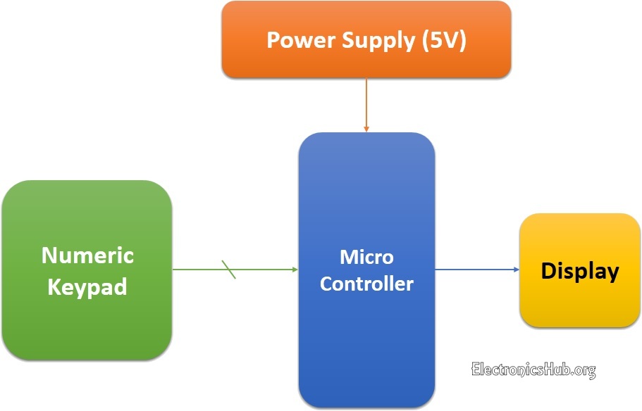
- Power Supply: It can be defined as a device that supplies electrical energy to one or more electric loads. The term is most commonly applied to devices that convert one form of electrical energy to another, though it may also refer to devices that convert another form of energy (e.g., mechanical, chemical, solar) to electrical energy. In our project a supply mains that is 5volt d.C. is given to the microcontroller, LED’s , keypad, display.

- Microcontroller: Microcontroller ATMEGA 16L is used for the automation purpose and acts as brain of the project. It controls the output (Display) according to the input given to it. Read the post: Microcontroller Basics to get basic knowledge about microcontrollers.
- Display: The Display used here is 3 Bi-color LED’s. The Glowing Pattern of LED’s represent the desired minimized expression.
- Keypad: In this project series of switches have been used as keypad, is used to give the input (min-terms) expression. Each digit on the keypad corresponds to one min-term each.

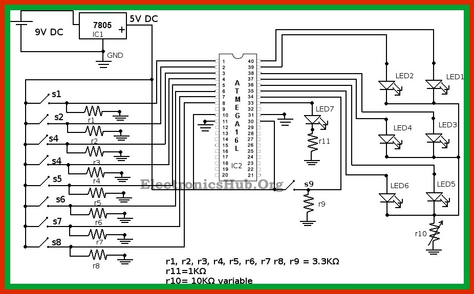
Circuit Schematic:This circuit is a simple 3 variable Boolean expression minimizer. It uses the Quine McCluskey algorithm which was described in the chapter 1.In this the microcontroller plays a major role, it consists of code to implement the described algorithm as well as controlls other components in the circuit.
Initially when the power is switched on an LED will glow which indicates that the microcontroller is ready to take the input. Here the input boolean expression is given in SOP form, i.e only min-terms are to be entered through the keypad provided.
The keypad consists of 9 switches of which 8 switches corresponds to one min-term each and the 9th one is used as next button.After entering the expression the input indicating LED will go OFF, now based on the algorithm microcontroller reduces the expression and the input representing LED glows which means that the expression has been minimized and is displayed.
The display consists of 3 Bi-color LED’s in which Green Light represents the variables in normal form and the rest Red Light represents the variables in the complemented form, the order of them is as shown in the circuit diagram.
The output is displayed as one min-term at a time, next min-term is displayed by pressing the next button and after reaching the last min-term of the reduced expression the input indicating LED is switched OFF which represents end of the output. After few seconds it is again switched ON automatically when microcontroller is ready to take the next input.
For more detail: Boolean Algebra Calculator
About The Author
Ibrar Ayyub
I am an experienced technical writer holding a Master's degree in computer science from BZU Multan, Pakistan University. With a background spanning various industries, particularly in home automation and engineering, I have honed my skills in crafting clear and concise content. Proficient in leveraging infographics and diagrams, I strive to simplify complex concepts for readers. My strength lies in thorough research and presenting information in a structured and logical format.
Follow Us:LinkedinTwitter