Summary of BOXOI – an Open Source Miniature 3D Zoetrope DIY Kit
In 2015, the author launched a Kickstarter for a miniature 3D zoetrope DIY kit to create a low-cost, space-saving optical toy. Although crowdfunding failed, the project evolved into an open-source instructable for makers and educators. The design utilizes wooden puzzles or 3D-printed parts to eliminate molding costs and simplify assembly. It features a custom PCBA with an Attiny85 microcontroller to control LEDs and a motor, offering an alternative BOXOI2-Lite mode using smartphone strobe apps if electronics are skipped.
Parts used in the Open Source Miniature 3D Zoetrope DIY Kit:
- Laser cut or 3D printed wooden puzzle plates (6 plates plus 2 x plate 5-2)
- THT electronic components including ATTINY85 microcontroller
- SI2302 MOSFETs (or compatible THT MOSFETs like SI2303)
- TCRT5000 photointerrupter sensor
- TT motor (3~6V, 1:48 reduction ratio)
- B type 15mm shaft potentiometer (100K ohm)
- Push button switch (red, m7)
- AA battery box (holds 3 batteries)
- LEDs (either 1W LEDs with aluminum plates or LED module 01.fzz)
- M3 x 25mm hex bolts and nuts
- PP round spacers (φ5x 6~7mm)
- Double sided foam tape
- O-shape PET sticker or packaging tape
- Wires with connectors
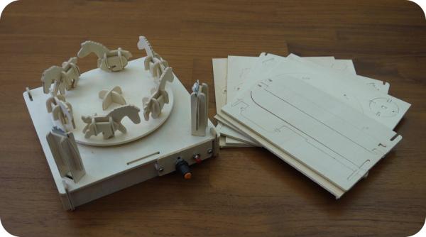
Project Background: In 2015, I started a kickstarter project of a miniature 3D zoetrope DIY kit. The next year, I started the version 2 of said project by further simplifying the kit and reducing its manufacturing cost. Sadly, both crowdfunding failed, but this is how the 3D zoetrope looks.
*Zoetrope: a 19th-century optical toy consisting of a cylinder with a series of pictures on the inner surface that, when viewed through slits with the cylinder rotating, give an impression of continuous motion. —Definitions from Oxford languages
The original idea was to make a low-cost 3D zoetrope for personal collection, that does not take much space at home, and does not collect dust easily. I made it into wooden puzzles to get rid of molding, painting, and assembly cost. Then I further simplify the assembly to make it a suitable science project for kids.
Purpose of this instructable: To make easy-to-biuild personal 3D zoetropes
For makers who want to build one for fun or for educational purposes, here you’ll find files needed as well as source files for modification purposes. If you have better solutions to make it more maker friendly, please feel free to improve my design and share with others.
For professionals who shares my view to make it a suitable science project for kids or companies interested in making this a product, feel free to take and modify any materials that I provide here for commercial purposes.
For others who simply found this project interesting, please share this link with your friends.
Step 1: Prepare the Wooden Puzzles
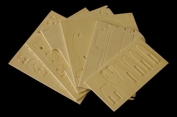
You can choose to either laser cut (and engrave) or 3d print the puzzles. Grooves/Slots in this design are 2.8mm in width, which is not too tight nor too loose for 3mm thick plywood sheets. I have not personally laser cut this one, and DXF files generated from Inkscape tend to be in wrong scales, so be sure to check scale before you cut.
For 3D printing, you’ll need a printer that can handle at least 185mm x 185mm. The 5 stl files are set to be 2.6mm thick because plastic printouts are harder than plywood sheets and inner cavities tend to be printed smaller. It may be a good idea to print a few pieces for testing then make adjustments to the thickness accordingly before you proceed to print the whole kit. I divided parts into 6 plates, 2 x plate 5-2 are required.
For people who do not prefer to spend the efforts to build the PCBA, I added a BOXOI2-Lite at the end of this instructable. However, here is the catch, you’ll need a good (maybe high-end) smartphone with a strobe light app as a substitute for the LEDs controlled by the PCBA. I personally tried this with my Nokia 3.1. Although the app is set to lit the LED for less than 1ms per (flash) cycle. My phone simply can’t catch up. The result is a blurry animation.
Step 2: Prepare the PCBA
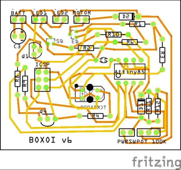
I’m not good with circuit design and programming, the plan was to demonstrate, get funding, then hire someone to redesign the circuit, use cheaper parts (attiny85 may be an overkill for this project), and rewrite the code. My apologies if the schematic and code look ugly.
All parts used in my circuit except for si2302 are THT parts, I think it’ll be more maker friendly and the parts are easier to get. I do think si2303 is very difficult to solder on a perfboard, but it’s doable. They are needed to handle higher current for the TT motor and LEDs, they also cause less voltage drop. You may replace these with other compatible THT mosfets, but the ones I found are too big and kinda overkill.
You can export BOM from the Fritzing file for shopping purpose. I can’t find TCRT5000 in Fritzing, so I use a phototransistor and an ir led to make footprint. Please ignore these two parts and find a TCRT5000 instead.
If you want to build this circuit on a perfboard (I tested it on a 5×7 cm board), be sure to measure the position for TCRT5000 before you start soldering. As shown in the photo above, there’s little tolerance under the platform for such big PCB, and the TCRT5000 has to go through a square hole on the platform. An easier approach is to make a TCRT5000 breakout board.
After the PCBA is completed, run Arduino and upload the sketch with ICSP. If you have no clue what this means, check online for tutorials about “programming stand alone Attiny85 with Arduino using ICSP”. You can also upload the sketch using a breadboard if you don’t have an AVR programmer. In that case, use a 8 pin socket instead of soldering Attiny85 on your PCB will be a good idea.
Step 3: Prepare Other Electric Parts, Nuts, and Bolts
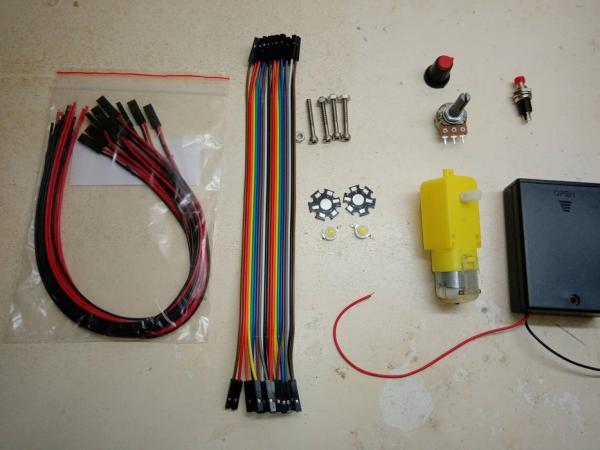
- One TT motor (3~6V, reduction ratio 1:48; ) – BOXOI runs roughly about 12 fps frame rate. So we need this motor to run 2~3 rps. (120~180 rpm)
- One B type 15mm shaft potentiometer 100K ohm
- One cap for the potentiometer (optional)
- One 2 pins push button switch (red, m7)
- One battery box (AA*3)
- LED x2 (either build PCBA versions with LED module 01.fzz or buy the 1W LEDs with aluminum plates)
- m3 x25mm hex bolts and nuts x4 sets
- PP round spacer φ5x 6~7mm(L) x2 (or make 2 with a 3D printer using the round spacer.stl)
- Some double sided foam tape to attach battery box and PCBA to the platform
- One O-shape PET sticker (or replace this with some packaging tape)
- Some wires with connectors
* Wires with connectors are to be solders to item 1,2,4,5,6.
Step 4: Build a Blank Play Disk
If the disk is 3D printed or laser cut without engraving, a piece of dark duct tape will do the trick.The dark stripe doesn’t have to be as wide as shown, about 1cm will do.
Step 5: Make the Ponies
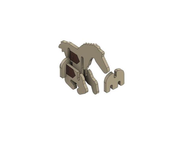
- Find yourself 3 parts with the same number, and 2 M-shaped puzzles
- All markings point forward (All numbers are closer to the tail)
- The markings on the leg parts are on the outside
- Finish all 6 ponies
Source: BOXOI – an Open Source Miniature 3D Zoetrope DIY Kit
- How can I manufacture the puzzle parts?
You can choose to laser cut and engrave them or 3D print them. - What is the recommended thickness for plywood sheets?
The design grooves are 2.8mm wide, intended for 3mm thick plywood sheets. - Can I use a smartphone instead of the PCBA for lighting?
Yes, you can use a high-end smartphone with a strobe light app, though results may vary by device. - Which microcontroller is used in the circuit design?
The project uses an Attiny85 microcontroller. - How do I handle the TCRT5000 sensor during soldering?
You should measure the position before soldering or make a breakout board because there is little tolerance under the platform. - What motor speed is required for the zoetrope?
The TT motor needs to run at roughly 2 to 3 revolutions per second (120 to 180 rpm) to achieve about 12 fps. - How many pony figures must be assembled?
You need to finish all 6 ponies using specific numbered parts and M-shaped puzzles. - What is the purpose of the dark duct tape?
A piece of dark duct tape creates the necessary dark stripe on a blank play disk if it lacks engraving. - Are the electronic parts through-hole or surface mount?
All parts except the si2302 are THT (through-hole) parts to make them more maker-friendly. - How can I modify the design for commercial purposes?
Professionals are free to take and modify any provided materials for commercial products or science projects.