Summary of Build Your Own Development Board
This article guides readers through building a custom development board using an ATmega88 microcontroller on a stripboard. It covers part selection, circuit design considerations like pull-up reset pins and power filtering, layout creation with StripCAD software, physical assembly steps, and programming via an ISP programmer using Atmel Studio. The process emphasizes understanding underlying hardware mechanics without requiring advanced tools.
Parts used in the Custom Development Board:
- Atmel ATmega88 processor
- Dip IC socket 28
- 10k ohm resistor
- 100 ohm resistor
- Diode
- Three 0.1 μF capacitors
- One 10 μF capacitor
- LED-diode
- 330 ohm resistor
- Jumpers
- Male or female pins
- Stripboard with strips
This instructable will show you how to build your own development board from scratch! This method is simple and doesn’t require any advanced tools, you can even do it at your kitchen table. This also gives a better understanding of how Ardruinos and other development boards really work.
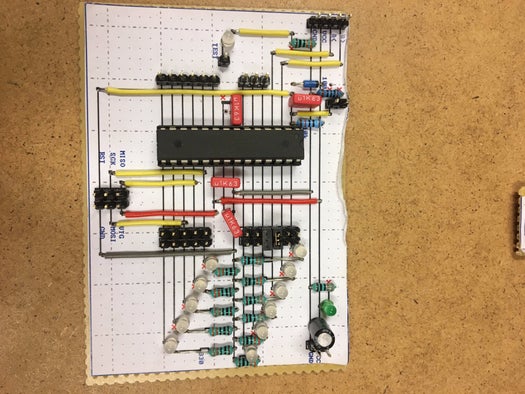
You can design your development board to fit your specific purpose. This development board shown in the picture was used to control the rpm of a DC-motor. The DC-motor was controlled from a computer using the serial port. The LEDs were used to assist when debugging was needed.
In this Instructable I will show how to build a versatile development board, therefore the part list will not be the same as the one shown in the picture.
Step 1: Parts
Part list:
- 1 Atmel ATmega88 (or any processor that best fits your needs)
- 1 Dip IC socket 28
- 1 10k ohm resistor
- 1 100 ohm resistor
- 1 diode
- 3 0.1 μF capacitor
- 1 10 μF capacitor
- 1 LED-diode
- 1 330 ohm resistor
- Some jumpers
- Some male-pins (or female)
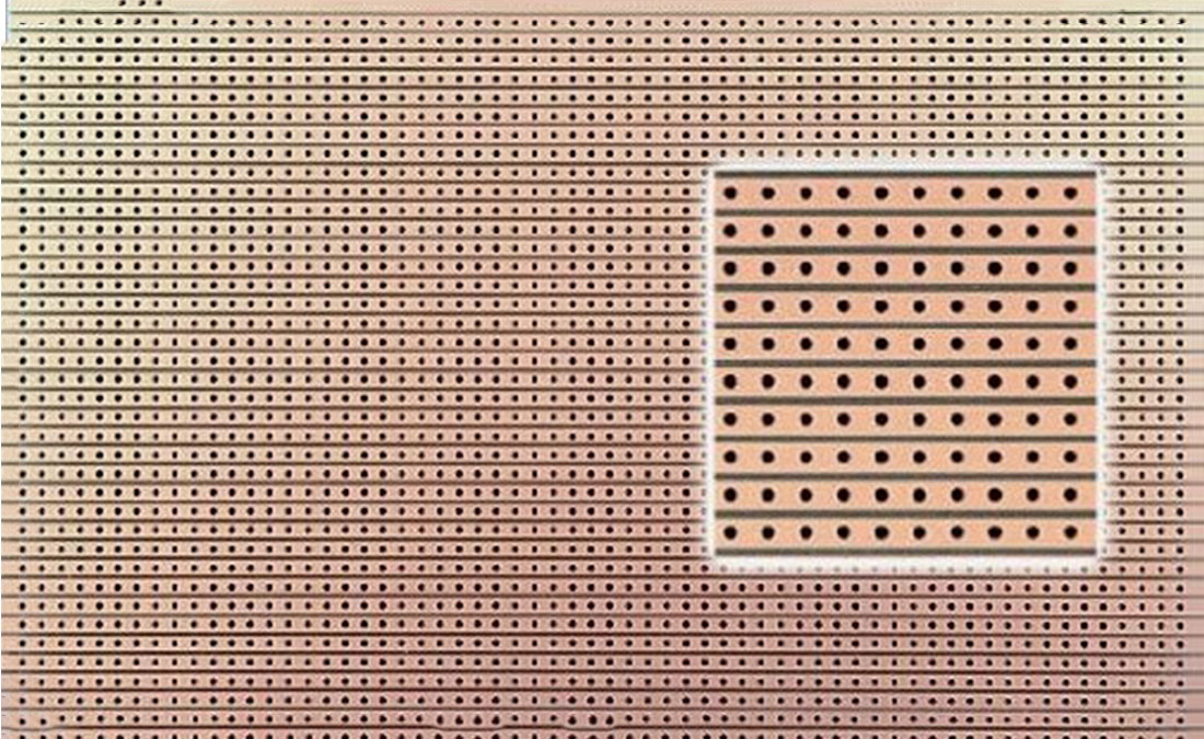
- A piece stripboard (use one with strips and not matrix, see picture)
To later be able to program your microcontroller you will need an ISP programmer (In-System programming). I used AVRISP mkII (http://www.atmel.com/tools/avrispmkii.aspx). There is a lot of different ISP-programmers to choose from, or you can build your own. There is also some ways to configuration an arduino to act as a ISP-programmer.
Step 2: Teori
To build and program a development board from scratch you will need to read some datasheets. It can sometimes be hard to find the thing you are looking for but I will provide the most important stuff.
ATmega88 datasheet
Hardware design consideration
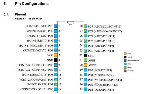
First we need to look at the pinout of the ATmega88 which can be found in the datasheet.
Some important ports that need extra consideration are the following:
Pin 1. This is the reset pin that will reset the processor when it is low. This pin will need a pull-up, so the the pin always is high unless you want to reset. (This will be shown later)
Pin 7 and 20 is where the Vcc should be connected, 5V.
Pin 9 and 10: To these pins an external crystal can be connected, but we will use the internal oscillator. We can therefore treat these pins as usual digital pins.
Pin 17,18 and 19: These will be used for programming (this will be shown later).
Step 3: Stripborad Layout
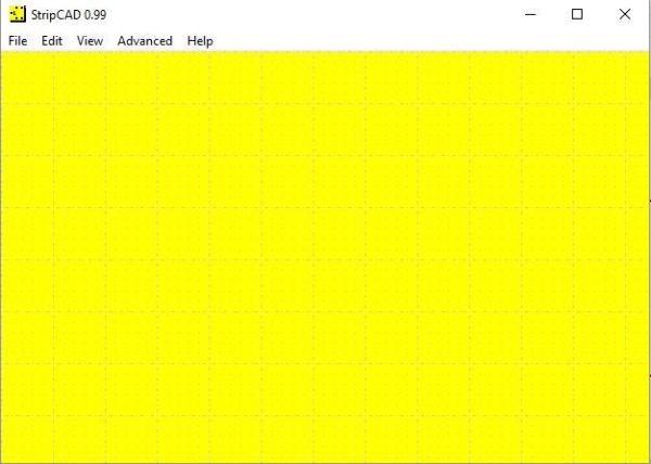
To create the circuit diagram we will be using StripCAD, follow link to download the program.
This program can be a bit hard to use since it isn’t user friendly, but it is effective when you know how to use it. Play around with it a bit and you will soon master it. Some good tips are the following.
- Press c to search for components
- Press v to obtain different variants
- Press left mouse click between two dots horisontal to get a disruption
- Press left mouse click between two dots vertical to get a solder bridge
When searching components:
- “DILxx” will give you a Dual In-Line followed by the number of pins
- “SILxx” will give you a Single In-Line followed by the number of pins
Otherwise just search for that component you are looking for.
Step 4: Pull-up Reset Pin
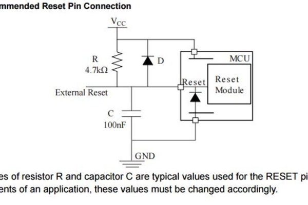
From the hardware design consideration document on side 6 we find the circuit in the picture. Read the text in the document to get a better understanding. This is the step were we handle the pull-up for pin 1.
It can be good to insert a manual reset for the microcontroller. This can be used by connecting a SIL2 in line with a 100 ohm resistor to ground. Short circuit the SIL2 with a jumper and the microcontroller will reset. The 100 ohm resistor will prevent the capacitor from short-circuiting. Otherwise just follow the circuit diagram from the document.
In the second picture the pull-up connection is illustrated in StripCAD
Step 5: Power Supply
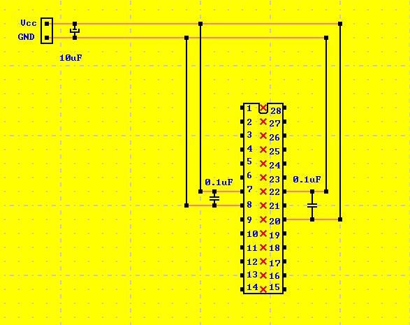
To avoid interference a capacitor 10 μF is placed near the voltage input on the board. To avoid interference that is caused in the board 0.1 μF capacitor is placed between pin 7 and 8, and between pin 20 and 22. These capacitors will act as a low-pass filter. The small capacitor should be placed as close to the pins as possible for best effect.
It is also possible to add some kind of voltage regulator e.g. 78L05, to make it run on a battery.
Step 6: ISP Programmer
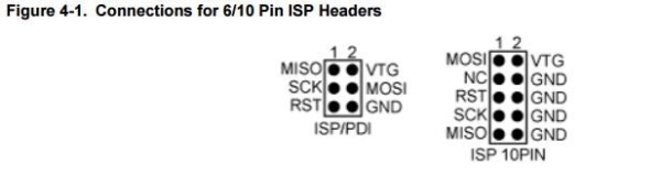
To program the processor you will need an ISP programmer. There is different connectors available, 6 pins or 10 pins. I used one with six pins, look at the hardware document to see how the connection should be designed.
ISP-programmer stands for In-System programming. The convenience with this type of a programmer is that you can program your device when it is installed in a complete system, rather than to have your chip installed before installing it to the system. It is also easy to reprogram once it is installed to the system.
See next step for how the ISP connection should be made.
Step 7: Layout
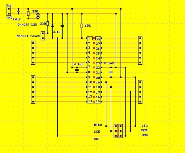
When the design is complete, press print to save it as a PDF (Or use attached file). Open the PDF-file and print it. Be aware that the printer setting should be set to actual size, otherwise the design will not match with the stripboard.
It is always a good idea to include a LED that shows if the power to the development board is on. That simple tip can save a lot of unnecessary debugging.
Steps to manufacture your own development board:
- Print out the circuit diagram, and use scissors to cut it out.
- Cut out a big enough piece of the stripboard, so the piece of paper fits on top.
- Position the paper over the stripboard so the holes corresponds, use an ordinary glue stick to attach the paper to the stripboard. Glue the paper to the side without copper strips.
- Start by making the disruption at the red crosses
- Follow up to build and solder from the lowest components to the highest, that will make the assembly easier.
- Hook it up to power supply (5V) and start to program.
Now the hardware of the development board is done!
Step 8: Programming
I used Atmel Studio for programming in C. Download the program and start to create awesome project with your own development board. It will be possible to boot-load arduino, but if you want a better understanding of what is hiding deep below in the arduino language try some examples in C. For example test out some timers,interrupts and analog reading.
In the ATmega88 datasheet you can find a lot of example codes for different specific tasks that your microcontroller can do.
As you can see this is a simple way to construct different prototypes for electronical devices. It is easy, cheap and doesn’t require special tools.
Source: Build Your Own Development Board
- What tool is recommended for creating the circuit diagram?
StripCAD is the program suggested for creating the circuit diagram. - How can I add a manual reset function to the microcontroller?
You can insert a SIL2 connected in line with a 100 ohm resistor to ground and short it with a jumper. - Why are capacitors placed near the voltage input and specific pins?
They act as a low-pass filter to avoid interference caused in the board. - Can I use an Arduino to act as an ISP programmer?
Yes, there are ways to configure an Arduino to act as an ISP-programmer. - What software was used for programming the microcontroller in C?
Atmel Studio was used for programming in C. - How should the paper template be attached to the stripboard during manufacturing?
Glue the paper to the side without copper strips so the holes correspond. - Is it necessary to use an external crystal for the oscillator?
No, the internal oscillator can be used by treating pins 9 and 10 as usual digital pins. - What is the benefit of using an In-System programmer?
It allows you to program the device when it is installed in a complete system rather than before installation.