Summary of Building Your Own Atmel AVR ISP Microcontroller Programmer
For beginners, the article describes building an AVR ISP programmer using an AVRJazz Tiny2313 board and modified AVR911 firmware to program an ATtiny13. It explains firmware tweaks, using AvrOspII software, fuse and configuration settings, and demonstrates driving an LED with ATtiny13 fast PWM. The guide covers hardware connections, programmer detection, and programming steps including fuse configuration, Auto Program options, and flashing the compiled hex to the target MCU.
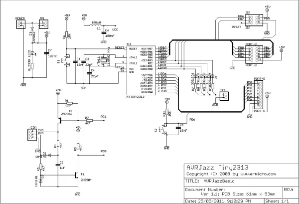
Parts used in the AVR ISP programmer project:
- AVRJazz Tiny2313 board (ermicro)
- AVR ATtiny13 microcontroller (target device)
- AVR ATtiny2313 (or ATTiny2313) on AVRJazz board as programmer MCU
- LED1 (connected to PIN 5 / OC0A of ATtiny13)
- Crystal oscillator for AVRJazz Tiny2313 (configured for 9.6 MHz internal RC or original 7.3728 MHz crystal reference)
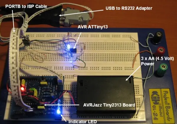
- Connection cable from PORTB of AVRJazz Tiny2313 to target ATtiny13 ISP pins
- PC or Notebook with USB or RS232 port
- AvrOspII programmer software (Mike Henning)
- AVR Studio 4 (for compiling assembler code and optional AVRPROG)
For beginners delving into AVR microcontrollers, one of the most challenging aspects is acquiring the AVR microcontroller programmer. The query typically revolves around how to program the AVR microcontroller. A Google search for AVR ISP Programmer yields abundant information, ranging from simple PC parallel port methods to sophisticated options like Atmel’s AVRISP mkII programmer. This often leads to the dilemma: which one to choose?
Choosing an Atmel AVR programmer involves considerations such as the number of supported AVR devices by the programmer’s software and how the programmer hardware connects to your PC/Notebook. Naturally, Atmel’s own AVR programmer tends to be the most comprehensive and optimal choice.
Atmel also provides an open-source AVR ISP programmer known as AVR911: AVR Open-source Programmer. The reference to the number “911” may indicate the significance of this topic. The hardware schema is available in their application note AVR910: In-System Programming. The original schema utilizes the outdated AT90S1200, and both the firmware (at90isp_ver23.asm) and the downloader (AVROSP.exe) support only a limited range of older devices. However, enthusiasts have updated this application note to support current devices, ensuring its relevance.
For this project, I’m utilizing the AVRJazz Tiny2313 board from ermicro as the foundational board for the programmer, with the AVR ATtiny13 microcontroller serving as the target device. The firmware, originally obtained from Klaus Leidinger at mikrocontroller-projekte.de, underwent modifications in the source code to ensure compatibility with the AVRJazz Tiny2313 board. These alterations primarily focused on adjusting parameters such as the ATTiny2313 microcontroller type (originally AT90S2313), crystal oscillator frequency (initially set at 7.3728 MHz), LED routines (initially designed for a dual-color LED connected to PORT B3 and B0), and the health-check function to initiate LED blinking five times upon startup. The complete source code and hex code are available for download here.
While the firmware operates efficiently with Atmel’s AVRPROG included in AVR Studio 4 (accessible from Tools -> Avr Prog…), this programmer supports only a limited range of devices. Additionally, it appears that Atmel may no longer update this program; the last update (version 1.40) mainly focused on supporting their new AVR Butterfly evaluation board using ATMega169. Consequently, I’ve opted for AvrOspII developed by Mike Henning for the latest Windows programmer version, which supports the AVR911 protocol. This programmer software is compatible with a wide array of commonly used AVR microcontroller devices.
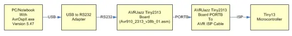
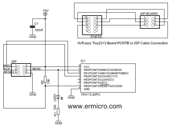
Below, you’ll find the hardware diagram, cable connections from PORTB of the AVRJazz Tiny2313 board (referencing the AVRJazz Tiny2313 schema above), and the schema for the ATtiny13 utilized in this project:
In this project, I’ll leverage the AVR ATtiny13’s fast PWM mode feature to control the brightness of LED1 linked to PIN 5 (OC0A). Below is the AVR assembler code:.
;*********************************************************************
; Program       : tiny13pwm.asm
; Description  	: Tiny13 Fast PWM Mode demo
; Last Updated 	: 30 November 2008
; Author        : RWB
; IDE/Compiler  : Atmel AVR Studio 4.14
; Programmer    : AvrOspII v5.47 from Mike Henning
;               : AVRJazz Tiny2313 Board with firmware
;               : Avr910_2313_v38b_01.asm Modified by RWB from
;               : Klaus Leidinger(mikrocontroller-projekte.de)
;*********************************************************************
.include "tn13def.inc"
; The Tiny13 Default Frequency Clock
.equ F_CPU = 9600000
.cseg
; Start on the flash ram's address 0
.org 0
main:   ldi R24,RAMEND         ; Initial Stack Pointer
	out SPL,R24            ; SP = RAMEND
; Initial I/O
        ldi   R16,0xFF
        out   DDRB,R16         ; DDRB=0xFF
; Initial PWM
        ldi   R16,0b10000011
	out   TCCR0A,R16       ; TCCR0A = 0b10000011
	ldi   R16,0b00000001
	out   TCCR0B,R16       ; TCCR0B = 0b00000001
repeat: ldi   R16,255          ; R16 = 255
bright: inc   R16              ; R16 = R16 + 1
        out   OCR0A,R16        ; OCR0A = R16
	ldi   R19,1
	rcall delay_func       ; Call Delay Function Parameter R19 = 1
        cpi   R16,255
	brne  bright           ; if (R16 <> 255) goto bright label
	out   OCR0A,R16        ; OCR0A = R16
	ldi   R19,1
	rcall delay_func       ; Call Delay Function Parameter R19 = 1
	clr   R16              ; R16 = 0
dark:   dec   R16              ; R16 = R16 - 1
        out   OCR0A,R16        ; OCR0A = R16
	ldi   R19,1
	rcall delay_func       ; Call Delay Function Parameter R19
        cpi   R16,0
	brne  dark             ; if (R16 <> 0) goto dark label
	out   OCR0A,R16        ; OCR0A = R16
	ldi   R19,50
	rcall delay_func       ; Call Delay Function Parameter R19
	rjmp  repeat
; Simple Delay Function
delay_func:
delay0: ldi   R20,25     ; R20 = 25
delay1: ldi   R21,255    ; R21 = 255
delay2: dec   R21        ; Descrease R21
	brne  delay2     ; if (R20 != 0) goto delay2 label
        dec   R20        ; Decrease R20
        brne  delay1     ; if (R20 != 0) goto delay1 label
	dec   R19        ; Decrease R19
	brne  delay0     ; if (R19 != 0) goto delay0 label
	ret              ; Return to the caller
.exit
Following the compilation of the provided code in AVR Studio 4, launch the AvrOspII program. If the connections are properly set up, the programmer will automatically detect the target ATtiny13 microcontroller. Alternatively, you can initiate the detection process by clicking on the “Auto Detect” button.
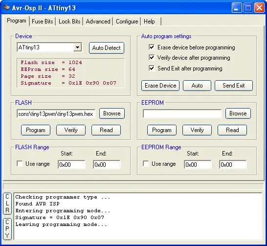
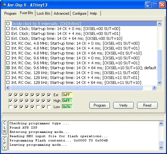
Before proceeding with the hex program download, review the Fuse Bits located on the Fuse Bits tab. Ensure that you disable the “Divide clock by 8 internally” option [CKDIV8=0] and opt for the default Internal RC oscillator at 9.6 MHz. Click the Program button to update the Fuse Bits, and then verify the changes by clicking the Read button once more.
Also check the configuration on the Configure tab as follow:
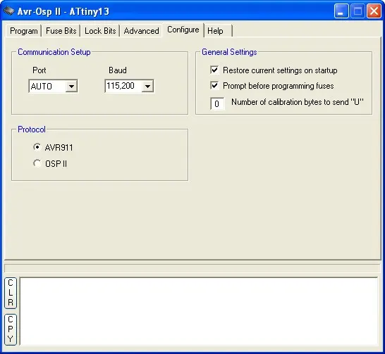
The Port is configured as AUTO, with a baud rate of 115200, and the protocol is designated as AVR911. Ensure that all the Auto Program settings (Erase, Verify, and Exit) are enabled on the Program tab. Load your hex file into the Flash fill-in box and initiate the download process into the target AVR ATtiny13 by clicking the Auto button.
Employing this method provides you with a robust Atmel AVR ISP programmer equipped with either a USB or RS232 port. Below is a video demonstrating the AVR Tiny13’s fast PWM mode.
- How do I program the ATtiny13 using this setup?
Compile the assembler code in AVR Studio 4, launch AvrOspII, ensure connections from PORTB of the AVRJazz Tiny2313 to target ATtiny13, auto-detect the device, load the hex into Flash, and click Auto to program. - Can AvrOspII detect the target ATtiny13 automatically?
Yes, if connections are correct AvrOspII will automatically detect the ATtiny13 or you can use the Auto Detect button. - What firmware is used on the AVRJazz Tiny2313 programmer board?
Modified AVR911 firmware (Avr910_2313_v38b_01.asm) originally from Klaus Leidinger, altered for the AVRJazz Tiny2313. - How should the fuse bits be configured before programming?
Disable Divide clock by 8 internally (CKDIV8=0) and select the default Internal RC oscillator at 9.6 MHz, then Program and Read to verify. - What protocol and port settings are used in AvrOspII?
Set Port to AUTO, baud rate to 115200, and protocol to AVR911. - Does the project support USB or RS232 connections?
Yes, the resulting programmer supports either USB or RS232 on the PC side. - What does the provided assembler code demonstrate?
It demonstrates ATtiny13 Fast PWM mode to control LED brightness on PIN 5 (OC0A). - Which software can compile the provided assembler code?
Atmel AVR Studio 4.14 is used to compile the provided tiny13pwm.asm code. - Are the source and hex files for the firmware available?
Yes, the article states the complete source code and hex code are available for download. - What programmer software was chosen over Atmel AVRPROG and why?
AvrOspII by Mike Henning was chosen because it supports AVR911 and a wider range of commonly used AVR devices; AVRPROG supports fewer devices and appears not recently updated.