Summary of Capacitance Meter using AVR microcontroller
This article describes a simple digital capacitance meter utilizing the integration method. By measuring the transient response time of an R-C network, the device calculates capacitance directly as digital data via a microcontroller. This approach eliminates the need for complex analog circuits and simplifies calibration, making it highly suitable for DIY construction compared to older methods like impedance bridges or dip meters.
Parts used in the Digital Capacitance Meter:
- Capacitor (Cx)
- Resistor (R)
- Switch
- Microcontroller (AVR)
- Power source (EMF E)
Digital Capacitance Meter
This is a simple capacitance meter which can measure capacitance value easy. There are some measurement methods for capacitance, at one time the capacitance was measured with a impedance bridge or a dip meter. Recently typical capacitance meters can measure capacitance and some additional characteristics from current vector by applying AC voltage to the Cx. Some simple capacitance meter use integration method that measureing transient response of the R-C network. There are some construction kits based on this method.
This project uses the integration method. There is an advantage that the resulut can be got as a digital data directly because it bases measurement of time, accurate analog circuit is not required and its calibration can be done easy by using a microcontroller. Therefor the integration method is suitable for hand built capacitance meter with high realizability.

Transient
The phenomenon appers until state of the circuit changes steady-state after state change, is called Transient. It is one of the fundamental operations of pulse circuit. When the switch in Figure 1a is opend, the capacitor C will be charged through the register R and voltage Vc will vary like shown in Figure 1b. To change state of the circuit, changing the value of EMF E instead can also be thought that equivalent. The relation between past time t and voltage VC is expressed in following formure.
![]() ———- (1)
———- (1)
Each units are: t seconds, R ohms, C farad and epsilon is a Napier’s number (approx. 2.72). When VC reaches VC1, the time t1 can be expressed in following formure.
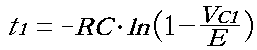 —– (2)
This means that the t1 is proportional to C. Thus the capacitance can be calcurated from charge time and any other fixed parameters.
For more detail: Capacitance Meter using AVR microcontroller
- How does this project measure capacitance?
The project uses the integration method by measuring the transient response time of an R-C network. - Can this meter provide digital data directly?
Yes, because it is based on time measurement, the result is obtained as digital data without requiring accurate analog circuits. - What is the main advantage of using the integration method?
The advantage is that calibration can be done easily using a microcontroller. - Does this design require complex analog circuitry?
No, accurate analog circuits are not required because the measurement relies on time. - What happens when the switch is opened in the described circuit?
The capacitor charges through the resistor, and the voltage varies over time until reaching a steady state. - Is the charge time proportional to the capacitance value?
Yes, the time t1 is proportional to C, allowing capacitance to be calculated from the charge time. - What older methods were used for capacitance measurement previously?
Previously, capacitance was measured using an impedance bridge or a dip meter. - Why is this method suitable for hand-built projects?
It is suitable due to its high realizability and ease of calibration via a microcontroller.