
Summary of Capacitive Touch with Atmel’s AT42QT1070 Touch Sensor IC
The article details the design of a custom capacitive touch breakout board using the Atmel AT42QT1070 IC. The author selected this chip over the MPR121 for its SOIC14 package and 5V compatibility, operating it in standalone mode to convert inputs into digital signals without I2C configuration. The project involves designing a compact PCB with minimal components to interface with microcontrollers like Arduino or Raspberry Pi.
Parts used in the Custom Capacitive Touch Breakout Board:
- Atmel AT42QT1070 Touch Sensor IC
- Resistors
- Capacitor
- Custom PCB
Rather than using an out-of-the-box capacitive touch solution for my projects, I thought I’d attempt making my own little breakout board. The idea is to use a sensor capable of triggering normal digital input pins using touch.
This post covers the selected touch sensor IC, the circuit used, getting a custom PCB made and how to use it in a project. At the end of this post, you’ll find a video covering the soldering and a brief demo of the custom board.
Touch Sensor IC
While searching for capacitive touch solutions, I quickly came across two different ICs: the Freescale MPR121 (as used in the Touch Board) and the Atmel AT42QT10XX. The MPR121 comes in a QFN package, immediately making it more difficult to use. It has up to 12 inputs and an I2C interface. It can operate from 1.7 to 3.6V making it slightly more difficult to work with when using a 5V host.
Comparing the specs of the MPR121 with the AT42QT10XX IC, I decided to pick the latter.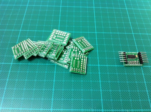
Atmel AT42QT1070
Some of the features worth mentioning are:
- SOIC14 package
- up to seven inputs
- fully debounced outputs
- suppresses effects of external noise
- touch sensing using single pin
- different operation modes (see next paragraph)
According to the datasheet, the keys can also be operated behing panels of glass (up to 10mm thick) or plastic (5mm).
And finally, because it can operate at voltages from 1.8V to 5.5V, it can be used in combination with a wide variety of boards, such as Arduino (5V logic level) or Raspberry Pi (3.3V logic).
Operating modes
There are two modes the touch sensor IC can operate in:
- comms mode
- standalone mode
In comms mode, the sensor can have up to seven input keys and interfaces with a master microcontroller or SBC via I2C. The I2C interface can for example also be used to configure sensitivity of the different input keys.
The other mode, standalone mode, does not make use of the I2C interface but rather converts up to five capacitive touch inputs into digital outputs. This is useful to convert digital inputs on a microcontroller board or SBC into capacitive touch inputs. Because the I2C interface is not used, sensitivity of the touch inputs cannot be configured and is static.
Different versions
Depending on the application’s required number of inputs, different ICs of the same family can be used.
Just to name a few:
- AT42QT1010: single channel
- AT42QT1040: four channels
- AT42QT1111: eleven channels
A full list can be found here: Dedicated Touch Devices
Schematic and Board
I chose to make a breakout board for the standalone mode. The circuit is simple as it only involves the touch IC, a couple of resistors and a capacitor. It was a bit trickier to fit everything in the smallest form factor possible, but that worked out well as you can see below.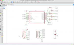
For more detail: Capacitive Touch with Atmel’s AT42QT1070 Touch Sensor IC
- Why was the AT42QT1070 chosen over the MPR121?
The AT42QT1070 uses an easier-to-handle SOIC14 package and supports 5V logic, unlike the MPR121 which is QFN packaged and limited to 3.6V. - What are the two operating modes of the AT42QT1070?
The sensor operates in comms mode using I2C for up to seven keys or standalone mode converting up to five inputs directly to digital outputs. - Can the touch sensor work behind panels?
Yes, the keys can operate behind glass panels up to 10mm thick or plastic panels up to 5mm thick. - How does standalone mode differ from comms mode regarding sensitivity?
In standalone mode, sensitivity is static and cannot be configured because the I2C interface is not used. - What voltage range does the AT42QT1070 support?
The IC operates at voltages from 1.8V to 5.5V, allowing use with both 3.3V and 5V boards. - Are there other versions of the AT42QT10XX family available?
Yes, different versions exist such as the AT42QT1010 for single channels, AT42QT1040 for four channels, and AT42QT1111 for eleven channels.
