Connectors
Everything has been mounted on a test board, including the headers for: ISP programmer (USBAsp), the 5110 Nokia LCD, the power supply (5V in, fed to the 3.3V regulator), the Reed relay connector, the reset button connector and another 2 pins connector, used to read the polarity of coil winding machine’s motor, so we know we either increment or decrement the counter.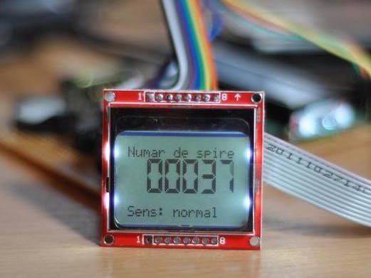
Connectors
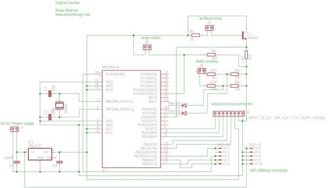
There are a few connectors:
J1: is for the power supply. The circuit takes 5V, that get into the L7833 for 3.3V output used by the atmega8 uC and the LCD.
J2: is the LCD connector, going to the Nokia 5110LCD.
J3: goes to the reed relay. This is the place we generate pulses for the microcontroller to count.
J4: is the polarity connector. It must be connected in parallel on the coil winding machine’s motor. It was designed for a 12V motor (but this can be changed by adjusting the voltage dividers formed by R3-R4 and R5-R6, so they take in the motor voltage, and output not more than 5V). If the motor is connected in normal polarity, we will read PD0 high, if the motor is in inverse polarity, we’ll have PD1 high. This info is used in the code to either increment or decrement the counter.
J5: is just a simple momentary switch. When pressed, will reset the counter to zero.
ISP connector: is a 10 pin connector used with the USBAsp AVR programmer.
Fuse Bits
External 8MHz crystal. The settings are:
avrdude -p atmega8 -c usbasp -U lfuse:w:0xff:m -U hfuse:w:0xc9:mVariant 1 : Atmega8 + Nokia 5110 LCD + 3V power supply
I am using an Atmega8-8PU (configured for 8MHz with external crystal), a Nokia 5110 lcd, and a transistor to handle the pulses from a reed relay. A 3.3V regulator provides the voltage for the entire circuit.
Variant 2 : Atmega8 + 2×16 HD44780 Character LCD + 5V power supply
Some of my readers asked for a custom variant, that uses a 2×16 HD44780 LCD (or a 1×16 smaller variant). These displays require a 5V voltage supply, so here is variant 2 of the digital counter, modified to support these requirements. See the images below.
Variant 2 images
For more detail: Coil Winding machine counter with Atmega8 and Reed relay