Summary of Composite Video Text/Graphics Display
The article describes a 40x25 monochrome composite TV text display built around an Atmel ATMega8 microcontroller (16 MHz). Character data is held in SRAM, fonts in Flash ROM, and the host communicates over an 8-bit parallel bus with strobe and busy signals. The design supports two font sets (Primary 256 DOS chars, Alternate 128 chars + inverse), non-interlaced refresh, and optional NTSC/PAL selection. Hardware uses TTL logic for latching, strobes, and an 8-bit shift register driving the video analog section; firmware and source are available.
Parts used in the Text Video Display:
- Atmel ATMega8 microcontroller (16 MHz)
- 1k SRAM (onboard ATMega8 SRAM used for character data)
- Flash ROM (ATMega8 program and font storage)
- 74HC573 Octal Latch
- 74HC74 D Flip-flop
- 74HC165 Shift Register
- 8-bit parallel data bus and connector (host interface)
- J3 NTSC/PAL jumper
- J4 Busy output logic level jumper (pins 1-2 or 2-3)
- Clock source/oscillator (16 MHz)
- Composite video analog circuitry (video output section)
The Text Video Display is complete! I’ve discovered a simple microcontroller and have taken a new approach to create a 40×25 monochrome text display. I am using an Atmel ATMega8 controller which contains 1k of SRAM and 8K of Flash ROM. I store the character data in the SRAM and the font is stored along with the program in the Flash ROM. The interface is an 8 bit parallel port with a strobe input and a busy output. It can be connected directly to a 65C22 8 bit port or any generic parallel port with ease.
While testing with the earlier circuits, I kept having problems with jitter while writing data from the host. I finally decided to drop the 74ACT715 and find a microcontroller that could handle the task. I tried a PIC 16F628, but it just didn’t have the horsepower or enough onboard RAM to simplify the circuit. The Atmel ATMega8 was perfect. It had just enough I/O and onboard memory to handle the task.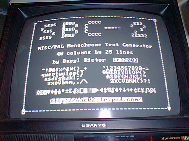
You can enable one of the two sets at any time. The primary font provides all 256 standard DOS characters, The alternate font provides 128 characters and the inverse of each. These are accessed by using toggle commands as defined below:
Lower = the lower 128 characters with the supported control characters (see description below).
Upper = the upper 128 characters including the box drawing characters in Primary mode, inverse characters in Alternate mode.
Primary Font Select = Enable the 256 DOS character set.
Alternate Font Select = Enable a subset of 128 characters with Inverse video support.
See the Command Bytes below for the specific toggle commands.
The display uses a non-interlaced refresh cycle which causes the pixels to be generated on every other horizontal line of the TV. For most smaller TV’s, this is not noticeable (as seen on the sample display above). However, you will notice this effect on larger TV’s (27 inch and higher). This is an example of what it might look like:

The firmware is complete and the prototype assembled and tested! Some last minute changes include increasing the clock speed from 14.318MHZ to 16MHz. This increased the horizontal border and display response. The source code for the ATMega8 is now available in the Downloads section. Here is a picture of the completed circuit. It measures just 2.5″ x 1.9″:
Here’s how the interface works:
The Host polls the Busy line and waits for it to go inactive (J4 selects active high or active low), then loads the data onto the data bus and clocks the strobe high. The Busy line will go active and stay active until the data has been processed. The time it takes to process a data byte depends upon several factors, including display refresh operations and display movements such as scrolling.
Here is a simple timing diagram:
The 74HC573 Octal Latch is not necessary as long as you leave the data inputs stable until the Busy Flag is reset, but I decided to add it to make the circuit more versatile. The 74HC74 D Flip-flop acts as the strobe latch and Busy Flag, which ensures the host’s strobes are not missed by the ATMega8 during screen refresh. It also divides the system 16MHz clock down to the 8MHz needed for the shift register. The 74HC165 shift register takes the parallel font data and shifts it out to the analog section to produce the video display. All timing and control is provided by the ATMega8’s program running at 16 MHz. J3 is left open for NTSC, and shorted for PAL. J4 selects the Busy Output logic level, short pins 1-2 for Active High or pins 2-3 for active low.
For more detail: Composite Video Text/Graphics Display
- What microcontroller is used in the project?
The project uses an Atmel ATMega8 microcontroller running at 16 MHz. - How is character data and font storage organized?
Character data is stored in SRAM and the font is stored in the ATMega8 Flash ROM with the program. - How does the host interface with the display?
The host connects via an 8 bit parallel port with a strobe input and a busy output and polls the Busy line before writing data. - What logic ICs are used for latching and shifting?
The design uses a 74HC573 octal latch, a 74HC74 D flip-flop, and a 74HC165 shift register. - How are Primary and Alternate fonts selected?
Fonts are toggled using command bytes: Primary Font Select enables 256 DOS characters; Alternate Font Select enables 128 characters plus inverse video support. - Does the display use interlaced or non-interlaced refresh?
The display uses a non-interlaced refresh cycle, generating pixels on every other horizontal TV line. - What changed to improve display response and border?
The clock speed was increased from 14.318 MHz to 16 MHz to increase horizontal border and display response. - How is NTSC versus PAL selected?
J3 is left open for NTSC and shorted for PAL. - How is the Busy output polarity selected?
J4 selects Busy logic level: short pins 1-2 for active high or pins 2-3 for active low.