Summary of How to configure Watchdog Timers of AVR Microcontroller (ATmega16)
This article explains the Watchdog Timer (WDT) in the ATmega16 microcontroller, a safety mechanism that resets the system if it enters an infinite loop or hangs. The WDT uses a separate 1MHz oscillator and configurable prescaler bits to set time-out periods ranging from milliseconds to seconds. If the program fails to reset the timer within this period, the system automatically reboots. The guide details the WDTCR register configuration, provides C source code for implementation, and describes a circuit with two LEDs to visualize normal operation versus a timeout event.
Parts used in the Watchdog Timer Configuration Project:
- ATmega16 Microcontroller
- LED
Some high end applications require multiple or critical calculations to be done by the microcontroller. This may lead to cases when the controller enters into wrong or infinite loops. As a result of this, the system either hangs up or gets crashed. The solution to overcome these situations is to automatically reset the system whenever such a situation arises.
The Watchdog Timer is a hardware or software generated timer interrupt which reboots/resets the system in the situations mentioned above. The watchdog timers are also used in cases when you intentionally require resetting the system without any physical interference.
The AVR microcontroller has an in-built watchdog timer. This article explains the working of watchdog timer in ATmega16.
The Watchdog Timer is a special timer which can be enabled in any section of the code and when enabled it ensures that a certain number of instructions execute within a pre-defined time frame. This time frame or the time delay can be configured/set using the registers of the watchdog timer. In case the instructions execute within the time frame, watchdog timer needs to be turned off and the program execution continues. However, if the instructions fail to execute within this time frame (this conditions is called time out condition) the entire system reboots thus avoiding any system crash or hang up.
Watchdog Timer in ATmega16:
The Watchdog timer of Atmega16 can be configured by using WDTCR register of AVR microcontroller. When the time out condition is set, the watchdog timer starts counting clock cycles. The watchdog’s timer is clocked from separate on-chip watchdog oscillator of 1MHz frequency. The time out condition is set by configuring prescaler bits of WDTCR register.
WDTCR (Watch Dog Timer Control Register):
|
–
|
–
|
–
|
WDTOE
|
WDE
|
WDP2
|
WDP1
|
WDP0
|
|
Bit 7
|
Bit 6
|
Bit 5
|
Bit 4
|
Bit 3
|
Bit 2
|
Bit 1
|
Bit 0
|
WDTOE (Watch Dog Turn-Off Enable) – The watchdog timer is disabled by configuring WDTOE and WDE bits (explained later in the article).
WDE (Watch Dog Enable) – Watchdog timer is enabled by writing 1 to WDE bit.
WDP [2:0] (Watch Dog Prescaler) bits – These three bits determine the watchdog time out condition. The table below shows prescaler bits combination and their corresponding time out period:
|
WDP2
|
WDP1
|
WDP0
|
Number of WDT oscillator cycles
|
Typical Time-out at Vcc=3.0V
|
Typical Time-out at Vcc=5.0V
|
|
0
|
0
|
0
|
16K (16,384)
|
17.1 ms
|
16.3 ms
|
|
0
|
0
|
1
|
32K (32,768)
|
34.3 ms
|
32.5 ms
|
|
0
|
1
|
0
|
64K (65,536)
|
68.5 ms
|
65 ms
|
|
0
|
1
|
1
|
128K (131,072)
|
0.14 s
|
0.13 s
|
|
1
|
0
|
0
|
256K (262,144)
|
0.27 s
|
0.26 s
|
|
1
|
0
|
1
|
512K (524,288)
|
0.55 s
|
0.52 s
|
|
1
|
1
|
0
|
1024K (1,048,576)
|
1.1 s
|
1.0 s
|
|
1
|
1
|
1
|
2048K (2,097,152)
|
2.2 s
|
2.1 s
|
How Watchdog Timer works:
The watchdog timer starts when the WDE bit is enabled and prescaler bits are configured for time-out condition. As watchdog timer reaches time-out condition, watchdog timer is reset and generates a pulse of one clock cycle which resets the program counter. When watch dog timer resets the timer, the WDRF (Watch Dog Reset Flag) bit in MCUCSR register is set by the hardware. To disable the watchdog timer following steps must be followed:
1. Set the WDE and WDTOE bits in same clock cycle WDTCR register. The logic one must be written to WDE bit even though it is set to one already.
2. After four clock pulses, write logic 0 to the WDE bit. Otherwise watchdog timer will not be disabled.
Objective:
To set watchdog timer condition at 2 seconds (approx.) and check the reset condition.
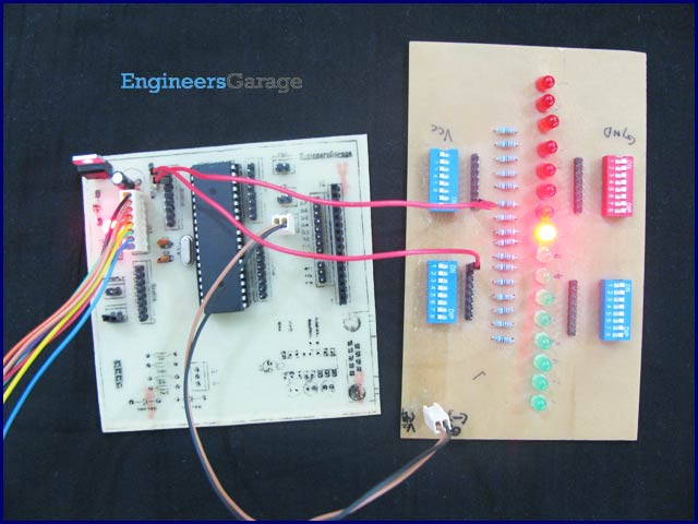
Circuit diagram:
The connection for above mentioned objective is shown in circuit diagram. An LED is connected at pin PB0 which blinks continuously. Another LED is connected to PB1 pin. This LED will glow when watchdog time out condition occurs.
Programming steps:
1. Check the status of WDRF bit. If this bit is high, set the PB1 pin of the controller.
2. Set the WDE bit in WDTCR register to activate the watchdog timer.
3. Set the prescaler bits WDP [2:0] = 111 for the time-out condition of 2 sec.
4. Write an infinite loop to toggle the PB0 bits toggles with a certain delay.
5. On time-out condition, watchdog timer resets the controller and this event reinitialize the program counter to go back at step 1.
Project Source Code
###
// Program to configure watchdog timer in ATmega16 Microcontroller
#include<avr/io.h>
#include<util/delay.h>
int main()
{
DDRB=0x03;
if(bit_is_set(MCUCSR,WDRF))
{
PORTB|=(1<<PB1);
_delay_ms(1000);
}
PORTB&=~(1<<PB1);
WDTCR=0x0F;
while(1)
{
PORTB|=(1<<PB0);
_delay_ms(400);
PORTB&=~(1<<PB0);
_delay_ms(400);
}
}
###
Circuit Diagrams
| Circuit-Diagram-of-How-to-configure-Watchdog-Timers-of-AVR-Microcontroller-ATmega16 |
For more detail: How to configure Watchdog Timers of AVR Microcontroller (ATmega16)
- What is the primary function of a Watchdog Timer?
It automatically resets the system when the controller enters wrong or infinite loops to prevent hanging or crashing. - How does the ATmega16 Watchdog Timer get clocked?
The timer is clocked from a separate on-chip watchdog oscillator with a frequency of 1MHz. - Which register is used to configure the Watchdog Timer in ATmega16?
The WDTCR (Watch Dog Timer Control Register) is used to configure the timer settings. - How can the time-out condition be adjusted?
The time-out condition is set by configuring the prescaler bits WDP[2:0] in the WDTCR register. - What happens when the instructions fail to execute within the defined time frame?
The entire system reboots, which avoids any system crash or hang up. - How do you disable the watchdog timer after enabling it?
You must set both WDE and WDTOE bits in the same clock cycle, wait four clock pulses, and then write logic 0 to the WDE bit. - Which flag is set by hardware when the watchdog timer resets the system?
The WDRF (Watch Dog Reset Flag) bit in the MCUCSR register is set by the hardware. - What code value sets the time-out condition to approximately 2 seconds?
Setting the prescaler bits WDP[2:0] to 111 configures the time-out condition to roughly 2 seconds.