
Summary of Control Electrical Appliances from Android Smart Phone using Bluetooth : Project Construction
This article outlines a project to connect a Bluetooth module to an AVR development board for controlling electrical appliances via Android. It details pin connections, uses LEDs for initial load state indication before switching to relays or triacs, and specifies the use of bi-color LEDs for system status. The setup requires two main modules plus a USB AVR Programmer to burn the hex file.
Parts used in the Bluetooth Module with Development Board Project:
- Bluetooth module
- AVR development board
- Four LEDs (for load state indication)
- Two bi-colour LEDs (for system status)
- Relays or triacs (optional replacement for LEDs)
- USB AVR Programmer
Connecting Bluetooth Module with Development Board
The Bluetooth module has seven interface pins of which two are NC (not connected) pins. The table below shows how you can interface with it our low cost AVR development board.
| Bluetooth Module | Dev Board |
|---|---|
| GND | GND |
| RST | PD2 |
| TX | PD0 |
| RX | PD1 |
| NC | |
| NC | |
| +5V IN | VCC |
Connecting Output Indicator LEDs
For initial testing purpose we will use LEDs to indicate the state of four loads. Once the testing is successfully completed then you can replace the LEDs with relays or triacs that can actually control the AC mains loads like light bulbs or fans. The load control outputs are available on the pins PD7, PB0, PB1, PB2
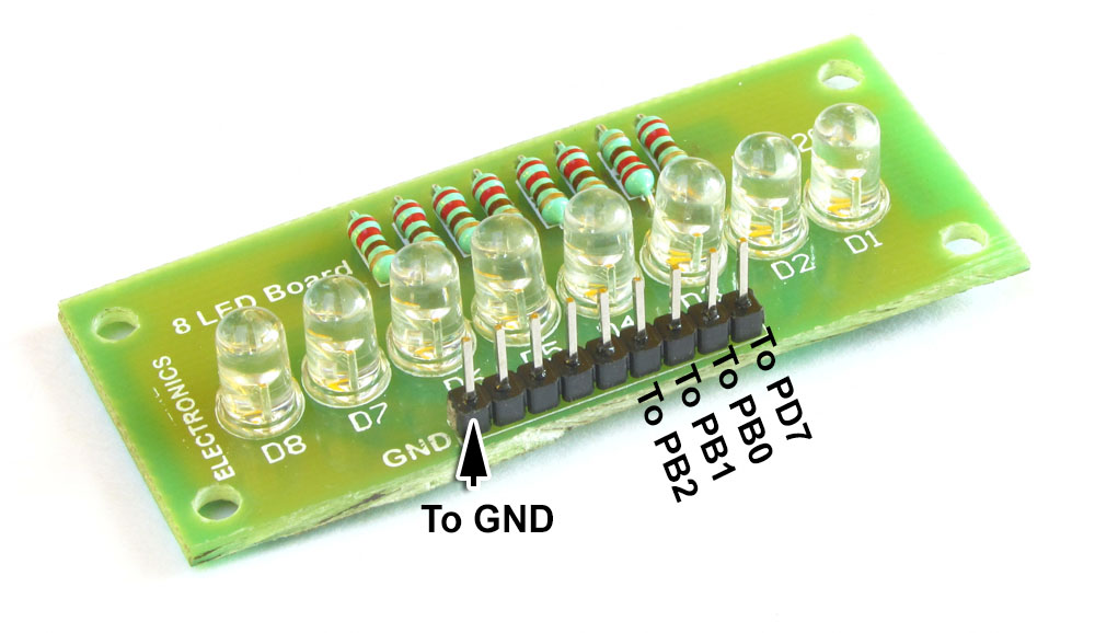
These are the only two module required to build this project. One more thing that you need is two bi-colour LEDs that will indicate the status of system. Please refer to the schematic for more details. After the connections are complete, download and burn the hex file for this project using USB AVR Programmer. Please refer to this video for the steps.
Schematic

We cordially thanks the following peoples who shared this page on various social networks and insprided us to develop more quality contents!
for more detail:Control Electrical Appliances from Android Smart Phone using Bluetooth : Project Construction
- How many interface pins does the Bluetooth module have?
The Bluetooth module has seven interface pins. - Can I replace the LEDs with other components later?
Yes, you can replace the LEDs with relays or triacs to control AC mains loads after testing is successful. - Which pins on the development board are used for load control outputs?
The load control outputs are available on pins PD7, PB0, PB1, and PB2. - What is required to burn the hex file for this project?
You need a USB AVR Programmer to download and burn the hex file. - Does the Bluetooth module have any unused pins?
Yes, two of the seven interface pins are NC (not connected). - What indicates the status of the system in this project?
Two bi-colour LEDs indicate the status of the system. - How do I connect the Bluetooth module TX pin?
The Bluetooth module TX pin connects to the PD0 pin on the development board. - What voltage is required for the Bluetooth module input?
The Bluetooth module requires +5V IN connected to VCC.
