Summary of CT Sensor on AVR ATmega
Summary (under 100 words): This article explains CT (current transformer) sensors and how to measure AC current with an ATmega microcontroller. It describes CT construction (primary wire, magnetic core, secondary winding) and explains relationships between primary and secondary voltages/currents via turns ratio and Faraday's law. The library performs RMS readings from the ADC, converts ADC voltage to RMS voltage, and computes primary current using Ip = V * Ns / Rburden. It also notes using a burden resistor to convert secondary current to voltage and shows a schematic with two 10k biasing resistors.
Parts used in the CT Sensor on ATmega project:
- CT sensor (primary single wire through core, secondary winding)
- Magnetic core (part of CT sensor)
- Burden resistor (Rburden)
- ATmega microcontroller (ADC)
- Two 10k biasing resistors
- Wiring to pass primary conductor through CT primary
A CT (Current Transformers) sensor is a device used to measure alternating current. A CT sensor, like other current transformers is made by a primary winding, a magnetic core and a secondary winding. The primary winding is often a single wire passing through the main core of the transformer. The seconday winding is used to sense the AC current passing through the primary winding wire. They are usually build to be clipped on the primary wire. As any other AC transformer the primary winding current produce a change in the magnetic field of the core. This change cause current on the secondary winding.

This library implements a way to read current using a CT sensor on ATmega.
It performs an RMS read on ADC, then computes the RMS voltage on ADC input.
So the primary current Ip is calculated by using the formula
Ip = V * Ns / Rburden
Given
Ns = Turns on secondary coil, i.e. the CT sensor core turns
Rburden = Burden resistor of the CT sensor.
Given
Vp = Voltage on primary
Vs = Voltage on secondary
Np = Turns on primary
Ns = Turns on secondary
Ip = Current on primary
Is = Current on seconday
CTratio = Np / Ns
From the Faraday’s Law
Vs/Vp = Ns/Np
And, due to conservation of energy
Vp*Ip = Vs*Is
So
Vp = (Np/Ns)*Vs
and
Vp = (Vs*Is)/Ip
Then
CTratio*Vs = (Vs*Is)/Ip
Simplified:
Is = Ip * CTratio
Using the ADC of our microcontroller we can read voltages, so we need to “convert” the current output of the CT sensor to voltage. We can doing this using a resistor, the burden resistor.
Below the schematics used on the ATmega sample.
Notice the two biasing 10k resistors.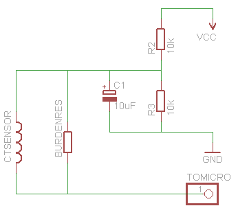
For more detail: CT Sensor on AVR ATmega
- What is a CT sensor?
A device made of a primary winding, magnetic core, and secondary winding used to measure alternating current. - How does a CT sensor produce a measurable signal?
Changes in the core magnetic field from the primary current induce current on the secondary winding. - How is the CT secondary output converted to a voltage for the ADC?
By using a burden resistor that converts secondary current into a voltage across it. - How does the library compute primary current from ADC readings?
It performs an RMS read on the ADC to get RMS voltage, then computes Ip = V * Ns / Rburden. - What formula relates secondary and primary voltages and turns?
From Faraday's law Vs/Vp = Ns/Np. - How are primary and secondary currents related?
Is = Ip * CTratio, where CTratio = Np / Ns. - What role do the two 10k resistors play?
They provide biasing for the ADC input as shown in the schematic. - What components constitute the primary winding in common CT sensors?
The primary is often a single wire passing through the CT core acting as a single-turn primary.