Some time ago I presented the Electronic Quiz I made when I was a kid. It can be used to solve quiz sheets. The big drawback is, that each number is hard-wired to one letter so there are 26 fix combinations. Those are fast to memorise, even more so if you are a kid. So I came up with the idea to built a version that allows to choose between different encryptions. I think that justifies to call it a decoder and opens up a few new creative and cool applications. Maybe I can use it somehow for a escape the room, a murder mystery game, a PnP session, …
You can also vary this project. Instead of a set of numbers and a set of letters you could also link two alphabets and implement the Caesar Cipher, Vigenère Cipher or the like (maybe outputting the decrypted letter via a 16-segment display). The possibilities are numerous.
Supplies
- uC-board (STM32F103 bluepill)
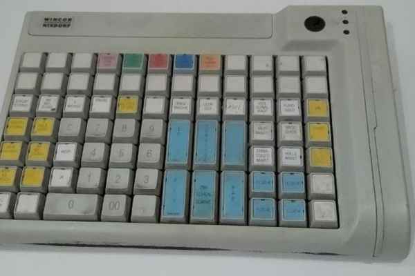
- cash register keyboard (Wincor Nixdorf PA84 PS/2)
- power bank (I wanted something flat – no huge capacity needed – so it has 2500 mAh)
- some LEDs, resistors, wires
- a on/off switch and a charge socket
- a laser cut frond panel
- a nice enclosure
- wood, aluminium bar, screws, washers, nuts, …
Tools
- uC programmer (STM21LINK V2)
- drill, thread cutter, saw
- soldering iron
- screw driver
Step 1: HW-Design
The functionality of the device was pretty much clear:
- there has to be a way to input a number and a letter at the same time
- there has to be a way to select one of several encodings
- the device has to show if the combination of number and letter is correct for the selected encoding
- ideally it also shows, when the combination is invalid
- if invalid inputs are possible, those can also be shown
Since I had the idea, I made a few designs. One was very close to the old hard-wired game. The idea to use discrete logic was dropped soon, when I calculated how many ICs I would need. As I learned more about uC it became clear, that this was the way I wanted to implement this game. It would have been possible to pull the inputs to high or low, using banana leads and sockets like I did in the old game. But buttons seemed to be a nicer input for a uC project. Both solution would have required a lot of pull-up or pull_down resistors and more inputs than the uC I use for tinkering feature. I could have used shift registers as parallel-series converters to get enough inputs or use a matrix like keyboards do, to reduce the number of inputs for 56 buttons (2×26 + 4 the select the encryption) a 7×8 matrix using 15 GPIOs would have worked.
Another idea was to use a rotary encoder to scroll to the alphabet and the numbers from 1 to 26. The current input would have been shown on segment displays. I could have either used two encoders or a switch to select what input I want to change. When the right combination is selected, I could have pressed a button to check, if it is correct. Encoders make it possible to detect if they a moved in one direction or the other by only processing two input binary signals. So they are a very elegant device to either increase or decrease a value in discrete steps. But it would have been less direct than hitting two buttons at the same time.
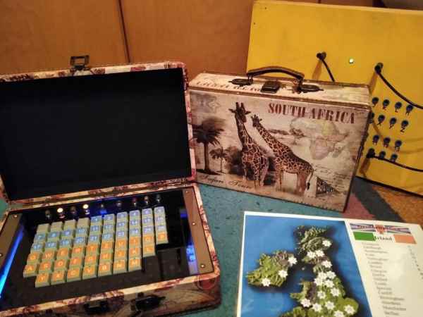
So I decided to use a device, that already does the scanning of a button matrix and outputs a simple to read and interpret serial signal: A PS/2 keyboard. I wrote already about the things I had to learn to use the in uC projects, so just check it out if you are interested. I did my first steps with a cheap foldable silicone keyboard but settled for something else. One of the pictures above shows my key layout and you might have noticed the nice arrangement in lines and columns you don’t usually see on keyboards. Pretty cool, isn’t it? But were do you find something like that? In the supermarket. Near the cash register. It is a part oft of the cash register. And of course you can buy it on ebay and the like.
Instead of buttons I could have chosen switches to select my encryption. Switches would hold the information of the selected code, when you turn off the power. With buttons it is always reset. That’s a matter of preference. I wanted to have LEDs to show the selected encryption anyway, because in my opinion a sequence of lit and unlit LEDs gives a nicer representation on the quiz sheet than switch settings. Because a equal number of buttons and LEDs makes it very intuitive to set the code from the quiz sheet I didn’t consider a rotary switch with multiple positions. And since I had many buttons to spare on my keyboard, I used some of those.
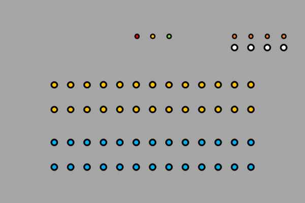
Because I have a lot of green, yellow and red LEDs laying around, I decided to use one of each kind. Green signals correct answers, red incorrect answers and yellow invalid inputs (more than one number or letter at a time). I got some orange LEDs that match optically but shine potentially much brighter. So they got significantly greater series resistors (green: 470 Ohm, red and yellow 150 Ohm, orange 1 kOhm, 3.3V supply).
To put it together this far and get the software running was not much of a challenge, because that are things I am used to do. All that was left to do was to pluck in a USB power bank and to put everything in a nice enclosure. And that’s the state the project had, when it went inside a cardboard box for a long time. For me the enclosure was more of a task, than the electronics. But at last I finished it an I am pleased with the result.
Step 2: SW-Design
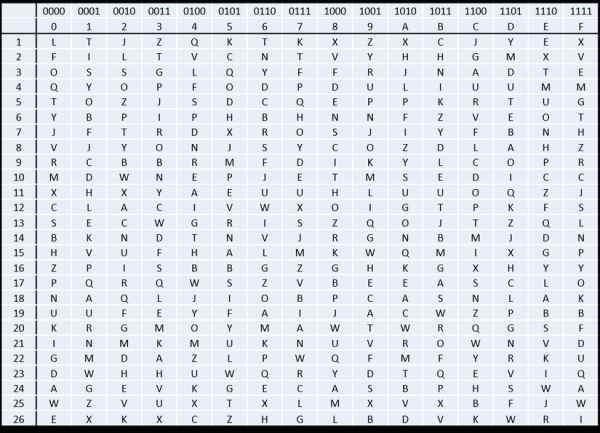
This projects first software is even older than the stuck together hardware. When I came up with the idea to build a new version of the game with different encryptions my siblings and I took out the scrabble game and made a lottery to get 15 new encryptions like I discipled in the instructable about the original quiz. I decided early on to use a 4-bit-4-button-4-LED hexadecimal code to select the encryptions and for code 0x00 the old encryption had to work obviously. The game had to be downward compatible so we can still use all those old quiz sheets.
As soon, as we had the tables of the encryptions, for convenience one in numerical and one in alphabetical order, we began to design quiz sheets. And to check those quiz sheets I made a little console application. I think no one besides myself ever used it. But it gave me pretty much everything I needed for my uC-SW-project minus the communication to the keyboard I describe in detail in my instructable featuring PS/2 keyboards.
The cash register keyboard is programmable and highly configurable. I bought 10 used ones at once, because that was the best offer at that time. I paid 29 € for all of them. I was lucky:
- The layout was similar for all keyboards.
- They all had 58 of the small keys with transparent covers I need for my layouts. I need 56 of them so I got enough without the need to canibalise additional keyboards. The rest of the keys has double the size and/or is printed (number block, Enter, …).
- The keyboards were programmed in the same way.
- There was a different code to all the possible key positions. As the double sized keys cover two positions and hit only one rubber dome, I could not be sure if some position would even generate output.
Since these keyboards where so similar, I guess they were discarded from the same store chain. It is lucky for me, because I built more than one of these games. And this way I had to read out the code of each key position only once. And I didn’t need to bother with programming this keyboard. I’m not even sure, if it would be easy to get the software to do so.
The cash register keyboard works a little different than the silicone one I used perviously:
- It has 2-key rollover so it will ignore all pressed keys, after the second is pressed. If that doesn’t work for you, you would need to scan the matrix on your own. You can get multiple-key rollover that way but more GPIOs are required. I have still 8 byte buffers for numbers and letters in my code. Those are really overdimensioned now.
- When a third key is pressed and one of the previous keys is released, the third key pressed will be output at that time.
- Make codes are not repeated. Since I ignore repeats, that is no problem, even welcomed. But I already put in some code to ignore repeats and left it, even if it’s needles now and makes the code a little more complicated to read.
Some testing showed, that if I hit the keys wildly, some unwanted events occurred:
- The PS/2 interface reset, because there was no idle state detected for 250 ms (a safety precaution built in by me). I made sure that the communication counter can be reset during every main loop run, when the communication is in idle state, while the counter is only increased, when a systick occured (once per ms). No unwanted resets occurred since then.
- The selected encryption was reset to zero with the PS/2 interface while the LEDs still showed the encryption selected before. I made sure, that the encryption is only initialized during boot up.
- Break codes can be missed in rare cases (when checking through all possible combinations fast). So the older entry in a buffer (letters or numbers) is deleted now, when both buffers together have more than two entries. That just can’t happen in error free operation, since the keyboard has 2-key rollover.
Instead of using the stdio library like the console application does, I read in the inputs via the PS/2 interface directly and output some signals using LEDs. Green LED instead of printing out “Correct!” Not much of a difference in the code. And the best thing is, I was able to just copy the 16×26 array with the correct combinations. Both codes are written in C.
I check if there is exactly one number and one letter in the buffers, if that holds true I check if the combination is true and set the according LED-output to high and the other LED-outputs to low. The number and letter to check are now element 0 of my buffer. In C arrays start with the element 0, so one more index can be used compared to starting with 1.
In my notation the letter associated to 1 is in the first entry (entry 0), the letter associated to 2 in the second (entry 1) and so on. So that’s were the [number-1] comes from.
Step 3: Disassembling and Modifieing the Keyboard
The used keyboards looked very used and the basic cleaning the seller mentioned in the desctiption was no cleaning at all. Or holding the keyboard upper side down, hoping that some dirt might fall out from it. But I wanted to disassemble them anyway. To do so, I needed a T 8 bit. The first one I opened quite some time ago and I didn’t have the huge bit set jet. So I used some small slotted screwdriver. It wasn’t a high quality one and you could see some wear around the edges afterwards, but it worked.
The keyboard also includes a key operated switch magnetic card reader. I don’t need them for this project so I just plugged them out and put them away for now. The keys come off easily and with a small slotted screwdriver I was able to remove the transparent covers from the backside. I threw the paper inlay away, as I will make my own later.
Then I put all the small plastic parts in a bag to wash them at low temperature of 30 °C and without spinning in the washing machine. I read this for Lego and yes, it works with keys as well. It might have been wise to wash the transparent covers and the keys in different bag, because many reassembled them self and I had to disassemble them once again.
Most of the keyboards I didn’t disassemble further. I cleaned them a little with the vacuum cleaner and if I felt like it, I brushed them and vacuum cleaned again. The black plastic protects the rubber domes quite well so it is okay to brush over it. But one of the keyboards I disassembled, was dead dirty. I disassembled it further to clean between the layers. I included the photos, as you can see the structure of the matrix. To unscrew the PCB I needed a T 10 bit.
To modify the keyboard I placed small keys with transparent covers where I need them, made and printed some nice paper inlays – for this one I used a typeset I saw in the instructable of Miss Betsy’s Steampunk Keyboard – an cut them out. For my prototype I used a guillotine cutter, now I have a cheap set of different formed hole punches. One of those fits – hmm… not really perfect, it isn’t even really spare. I have to trim with the scissors, but it is okay. With the guillotine cutter I tended to make them a little too small, so I didn’t have to cut corners afterwards. That’s less alluring with the punch so I get inlays, that cover more of the space and I’m quite happy with the result. The key design with the frames is a little tricky. If you don’t get it centred well or it is a little inclined, it’s easy to notice.
Step 4: Designing the Enclosure
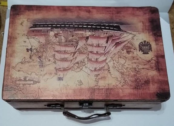
I like my keyboard design. The numbers are in numerical orders and instead of arranging the letters by alphabet I used the usual keyboard design (the German one with Y and Z swapped). But it has a few corners and when I first tried to cut out a front panel from MDF with a jigsaw I miscut and the project went into a cardboard box for a few years.
To buy a laser cutter to make a few front panel would be a little overkill, but some time ago I had the idea to search through the web, if there are supplier of laser cut acryl sheets at a reasonable price. A few Euro more or less are less of an objective, as it was a few years ago. I found some suppliers with web based configuration tools, but I didn’t like those through to the limitations. No holes under 5 mm or closer than 20 mm to the edge and the possibility to cut out rectangular shapes, also with rounded corners, but no possibility to round the corners, where two rectangles cross each other. Then I found one, where I could upload a CAD-drawing and it calculated the price right away. I went with this one.
Now I knew, where I will get my hopefully nice front panel. But a enclosure is more than just a nice front. I had to get some kind of box. I could have built one, but I preferred to get something ready with a good size. The biggest part, that must fit inside, is the keyboard. And there has to be some space around the keyboard to fit in other elements like the LEDs, an on/off switch and a charging socket. The power bank and the uC board must fit in the housing. During my search I came to the conclusion, that something with a lid would be nice. It would prevent dust from piling up between the keys.
The keyboard is circa 235×150 mm. Because I don’t want to jam the flex wiring of keypad, I calculated with 235×160 mm. To the left and right of the keyboard I would need some space for the frame. I found some small wooden suitcases with a variation of motives. The Idea to build the different games for me and my siblings with the same measurements and get different looks was quite appealing.
So I got one of those. 310x20x10 cm seemed to promise enough space without being to bulky. But I won’t trust in measurements from some web store without seeing at least a data sheet. So I measured, when I got it. The tolerance was quite okay for a wooden decoration suitcase and the side panels are about 8 mm thick. So it has inner measurements circa of 294 to 184 mm. For my prototype I decided on a front panel size of 192×182 mm to have some leeway to middle things out. And a rounded corners with a 3 mm radius.
I had to measure out the dimensions of the keyboard carefully. It is a little tricky as the keys are a little shifted as soon as you touch them with the sliding calliper. After I checked and checked again I was quite sure, that the keys are 18 mm wide and 1 mm apart. I decided to leave a gap of 1 mm between around the keys. So I can calculate with approximately 19 mm per key. If I want to know the width without the outer gap, it is -1 mm and if I want to include the gap it is +1 mm. The width of the clearance for 10 keys is 191mm. I rounded all corners around the key field with radius of 1 mm.
I middled it out and made the clearance for the keyboard as low as possible to have maximal space to place other elements above the keyboard. From left to right those are:
- charging socket (8.4 mm hole in accordance to the data sheet)
- 4 orange LEDs to show the selected encryption (central above the corresponding keys, 8.2 mm holes after measuring the sockets)
- LEDs red, yellow, green (central above the 3 outer keys on the right, 8.2 mm holes)
- on off switch (6.2 mm and 2.4 mm holes, distance 6.4 mm, in accordance to the data sheet)
The mounting holes on the sides are 3.2 mm in diameter and 12 mm from the edge. I use 3 mm wood screws to fix the panel. This is the revised design. The prototype had the switch and the charging socked in the space between the orange LEDs and red LED. But that’s the spot, where the panel is the weakest so it bends a little when you plug in the charging cable. That’s why I shifted those elements to the side. The switch is on the right, because there it is the most intuitive to reach for an right-handed person. Aside from changing the placement of two elements I could keep all measurements because it fit well in the suitcase. And the suitcases I ordered after assembling the prototype had good enough tolerances.
The mounting construction consists basically of 20×20 mm spare wood (beech) and 10×10 mm spare aluminium. The aluminium is used, because I have to fit it trough the key pads flex wire and can’t make it thicker. I use also a few centimetre of 20×13 mm wood, 15×15 mm wood, a piece of MDF, wooden skewers, spacers and PCB mounts to mount the power bank and the uC board and to bring the keyboard close to the front panel.
Step 5: Assembling the Game
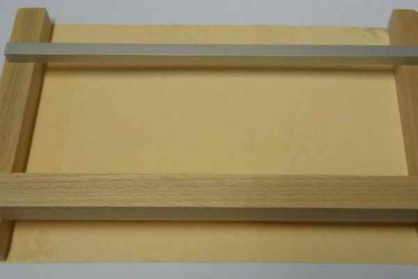
First I got the three wooden bars and the one aluminium bar ready. It is a good Idea to think early about the placement of your holes. After assembling the bars some points are difficult to reach with the drill and I don’t want to hit a screw with another. So I drilled most of the holes in advance. Of cause I forgot one or two, but that was okay.
I had a sheet of paper cut to the inner dimensions of the suitcase, so I could align the bars and then screw them together. I mounted the wooden bars first and screwed the keyboard centred to the aluminium bar. I used some 5 mm spacers + M3 washers to bring the keyboard as close as possible to the level of the front panel. I glued them in place with superglue, because otherwise it’s a pain to get those small parts in place all the time. If you don’t have thread cutters you can use super glue to stick nuts to the backside of the aluminium bar and work with simple holes. I did so when I assembled the prototype. The nut might come off, when you tighten the screw, but that is okay, since the nut is already in place. But if you have to dismount the keyboard again and the nuts falls down, it’s annoying.
I brought the frame to a plane level inside the box using some pieces of wood. I could still shift the keyboard around a little, since the aluminium bar was not connected to the wooden elements yet. The width of the aluminium bar is a few millimetre less than the inner width of the suitcase to have some tolerance. I put the front panel on top and tried to centre everything. Then I put the front panel off again an screwed the keyboard to the wooden bar. Then I flipped the framework to fix the aluminium bars to the rest of the construction.
Then I fixed the MDF sheet to the bottom side, to make sure that nothing deforms, when I dismount the keyboard, and mounted the power bank and PCB mount. Then I got the electronics ready. My main source of wires was an pre-configured cable harness of four wired flat band cables. I’m not sure where I got it. To connect the keyboard I cut the PS/2 cable, that came along, to a fitting length and soldered it directly to the uC board. To connect the power bank I used a micro USB socket breakout board to connect the output and cut a micro USB cable for the charging input. I used the rest of the cable later on to make a cable for charging, that can be used with a common USB charger.
I mounted the uC board, connected the power bank and begun to screw the frame to the suitcase. Screw clamps were essential to fix the frame at the right hight and to hold it tight to the side panels while the screws cut in.
Next I added the LEDs, the switch and the charging socket to the front panel. Since I had to remove the protective film I had a cloth ready, so I could put the panel down at a place, where it won’t scratch. Then I connected the series resistors and the wiring of the panel elements. I used the connectors of the wire harness so I can remove the front panel with all elements, when I disassemble the box.
Before I fixed the keyboard, it would have been a perfect time to vacuum clean the inside of the box. I had to dismount the keyboard once again. But I fixed all wires at least. And yeah, I put some yellow LEDs under the keyboard, but I have to exchange them for brighter ones because you don’t see much of them.
Update: I exchanged the LEDs by now and included a image of the illuminated quiz.
It is good idea to check the functions and clean the inner side of the front panel with some microfibre cloth before you fix the front panel. I centred it once again to get a regular gap around the key field, pre drilled the wood an put in some screws with a shiny head. I like the mix of the vintage suitcase, the see through electronics and the pattern of the unequipped parts of the keyboard. In my opinion it looks quite nice.
Step 6: The Prototype

Just because it featured adequately bright LEDs underneath the keyboard and the option to put quiz sheets in the lid with magnets first. Sadly DIN A4 paper doesn’t fit in. But That was not enough of a reason to go for more bulky boxes.
Update: For the ferromagnetic strip to pin sheets I used a self adhesive steel ruler. It was a rest that was left after I used the part starting from zero on the front edge of my work bench. This way I have always a ruler for fast measurements at hand. I stuck to strips of the ruler next to each other in the lid to get a wider magnetic area and covered them with black cloth tape. To get the tape to the right length I stuck a longer piece over the lids sideboards and cut along the inner edges of the sideboards with scissors.
Source: Decoder / Electronic Quiz Game 2.0