I. Introduction
The goal of this project is to build a digital compass that displays both the direction and cardinal points on a television. Other functionalities were added to complement the sensor interface, such as, temperature display, magnetic declination input and disability option.
At the highest level, this project involves acquiring two output readings from the Hall-effect sensor (Dinsmore R1655) and processing the data through the ADC and output the directional information onto a TV screen. The first part involves amplifying the two output voltages and feeding them into the Mega 32 ADC input. After that, extensive calibration was necessary to accurately decode the input voltages into useful directional information. A mapping was done to the flash memory to retrieve the direction accordingly to different sets of inputs. As a matter of fact each pair of inputs were unique, so mapping them made sense as timing is an issue when using the TV as an interface. Finally disability option was added to bip at different frequencies depending on the desired direction entered by the user. Additionally adding a magnetic declination feature enables the compass to display the true north rather than the magnetic north as a function of current location.
II. High Level Design
1. Idea and Motivation
Our motivation originated while surfing through Amazon.com and checking the Electronics Section. We came upon a cool digital compass but the price wasn’t. Upon that day we decided to replicate it by using a sensor and integrating into Mega 32. Ideally we wanted to display on a graphical LCD but due to the budget constraint we restrained ourselves by using the TV provided in the lab.
2. Design Overview
The core of our project centers around the hall-effect sensor. Basically the sensor outputs a sine-cosine curve pair which may be interpreted by Mega 32 into directional information. The sensor requires a regulated 5 V DC input, hence we used the voltage supplied by the STK 500 board. The first trick involves reading one channel at a time in ADC. This was accomplished by toggling the channel each time a data is read. After that calibration of the compass was done, this part involved recording the ADC value every 10 degrees. A simple interpolation scheme was performed on the acquired data in Matlab.
The interpolated values were then exported into the flash memory and mapped accordingly to the input channels. Each input channel would retrieve two possible degrees from memory since we are dealing with sine-cosine functions. These four values (two for each channel) are then compared using a simple algorithm and the correct degree information was passed onto the screen using schemes learned in Lab 4. After some debugging and verifying the accuracy of the displayed value, we went on to display the circular plot with the eight cardinal points plus a directional pointer.
After we successfully got the sensor to work with the display, we decided to incorporate additional features that would improve the user interface and the practicality of the digital compass as a standalone application. First we added a disability option. This feature enables a person with visual disability to interface with the digital compass. The user can enter a desired direction (N,E,S or W) and the digital compass would bip according to the proximity of the current direction to the desired direction. The bip sound was designed to be as a function of both frequency and pitch, that is, the higher the frequency and pitch the closer you are to the desired direction.
Lastly, we added a magnetic declination option in order for the digital compass to display the true north. This feature is initialized to 11 degrees West (Ithaca, NY) and the user is allowed to adjust by pushing two of the buttons on the STK 500. Adjustments to the previous readings were made accordingly to display the direction correctly.
3. Hardware/Sofware Tradeoffs
The use of TV in place of a graphical LCD proved to be viable, but with limited capability and user interface. The main advantage comes from the fact that the TV was used in Lab 4, hence some of the code could be re-used and the knowledge and experience proved to be invaluable.
In terms of software, we decided to re-use some of the codes provided by Professor Land and code entirely in C rather than assembly. This limited the functionality of our design due to time constraint, but at the same time it eased the complexity of our project.
4. Standards
The main standard used in the project is the RS170 composite video standard and the NTSC frame rate. Our video signal is non-interlaced, black and white video. The standard requires 3 voltage levels to generate sync, black and white signals along with horizontal and vertical sync pulses. All drawings must be carried out during TV scan line 230-260 and 1-30 to avoid visual artifacts.
5. Patents and IP
Robert C. Dinsmore holds a patent for portable electronic compass. His invention comprises battery operated compass utilizing Hall effect digital switches to sense the orientation of the compass in relation to the earth’s magnetic field. Decoding of sensor output were used for alphanumeric display.
Though our digital compass has similar feature found in Dinsmore’s invention, we believe our approach and design are completly different. However, we credit the usage of his intellectual property as the basis of our project. Additionally we need to credit Professor Land for supplying the core code for the TV display in Mega 32. We used his code as the starting point for our project.
III. Program/Hardware Design
1. Program Details
The core of our program was derived from Professor Land’s demo code provided in Lab 4. The first modification was to enable the ADC to read three channels. A simple state machine with switch statement was used that basically changes the ADMUX channel selection after it reads a channel input. For example, when channel 0 is read, we change the ADMUX channel to 1, so that the next time around the switch statement enters to channel 1 case and reads its value.
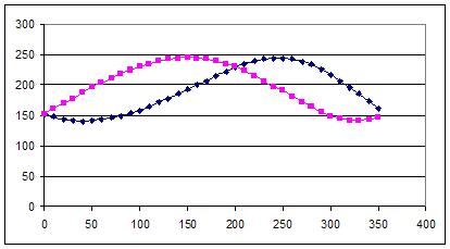
After verifying the functionality of the ADC reading, we calibrated the analog sensor by taking a reading every 10 degrees. Figure 2 below depicts the two output curves obtained from the ADC:
Next part involved using the data collected above and interpolating the values between each reading. This was accomplished by using Matlab. The result was then put into flash memory for easy access. An algorithm was required to compare the four directional values from the memory and picking the right value to display on the TV. This proved to be tricky since the interpolatd value were not ideal and manipulation on the data was necessary. To put it simple we took the difference among all four values and used this information to pick the correct direction to display. More details can be found in the code.
The circular plot and the directional pointer was first done in Matlab and then transferred into C program. For the pointer, we basically needed an end-point since the starting point is always fixed in the center of the circle. So in Matlab we simulated such situation, which would give us all the end points required for a line to be drawn from the center. These end-points were also stored in the flash memory to provide easy access from the main loop. A picture of the simulated circle plus the direction pointer is shown in Figure 3 above. A demo movie of the digital compass been operated can be seen here.
Adding sound into the digital compass provided a nice feature to the system. We used the TCCR0 and OCR0 to produce the bip sound. Frequency and pitch were adjusted accordingly to reflect the current position with respect to the desired location. We also added a feature that blinks in the direction that the user wants to go. Also under this mode of operation the circle has four cardinal points around it as shown in Figure 4 below. Here is a link that demos the compass operating with the desired direction set to North.
The magnetic declination involves detecting the push button on PORT C and adjusting the output reading found above according to the amount of declination. This part is a little tricky since our design involves mostly mapping. The main issue comes in finding end-points stored in memory for the directional pointer. This can be solved by correctly adjusting the value if it is either positive or negative. Here is a link of magnetic declination been adjusted by a user.
Lastly, the temperature sensor was added into the system. This proved to be the easiest task since we dealt with this component in Lab 5 and integrating into the digital compass was easy.
2. Hardware Details
This part may seem to be trivial initially because most parts were used previously in our labs, except the compass sensor. The sensor required a lot of work to get it to work reliably. At first we hooked up the sensor onto the breadboard, and added some gain to both output signals in order to make use of the full range of the ADC converter. Low-pass filter was also necessary to filter out some of the noise present in the signal. Calibration was done as mentioned above. This method proved to be inaccurate since the sensor was very sensitive to even slight displacement on the breadboard.
A new method was used to hook up the sensor onto the breadboard. This involved drilling tiny hole into a plastic cap and mounting the sensor onto it, as shown in Figure 5 below.
For more detail: Digital Compass