Summary of DIY NES Classic Advantage Controller
This article details a DIY project to build a custom NES Classic Edition controller inspired by the Nintendo Advantage. The creator designed this to overcome lag and reliability issues with third-party controllers. Key features include an adjustable turbo function (1–35 presses per second) and a dedicated home button for accessing the NES Mini menu without resetting the console. The project utilizes an Atmega328P-PU microcontroller, arcade-style Sanwa components, and a 3D-printed enclosure.
Parts used in the NES Classic Advantage Controller:
- Atmega328P-PU microcontroller
- 0.1uF capacitor
- Mini Panel Mount SPDT Toggle Switches (2)
- B10K Panel Mount Potentiometers (2)
- Perfboard
- Sanwa JLF-TP-8YT joystick
- Sanwa joystick top (Ball or Bat)
- Sanwa OBSF-30 Buttons (2)
- Microswitches (3)
- 5mm LEDs (2)
- 4-40 screws (various sizes)
- Wii controller cable
- 1/8" metal rod
- Wire
- Optional: 2.54mm pin headers, DuPont connectors, IC socket, heat shrink tubing
- Tools: Hobby knife, tap, screwdrivers, files, hot glue gun, AVR programmer
A Nintendo Advantage inspired controller to use with the NES Classic Edition, also known as the NES Mini. This project is based off of the Wii RetroPad Adapter project by Bruno Freitas. I made this because of bad experiences with 3rd party controllers lagging and/or just not working.
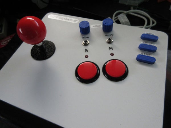
Main “Advantages” over the stock controller and some other 3rd party controllers:
- Turbooooooo – On/Off toggle and adjustable rate from 1 to 35 presses per second (range can be changed)
- Home Button – Return to the NES Mini menu screen to change games or save states without having to press Reset on the console
The NES Classic Advantage Controller project uses an Atmega328P-PU microcontroller to emulate a Nintendo Classic controller but without the X/Y/L/R buttons and analog sticks.
I also made a 3d printed enclosure for the controller. The CAD and STL files are on Thingiverse. Instructions on using the enclosure are in this instructable. If you don’t have a 3d printer, check out SlagCoin.com. SlagCoin is a great resource for building joysticks.
Step 1: Bill of Materials & Tools
Please support your local or in-country venders as I know you may get most, if not all of the materials cheaply from eBay. The 3d printed case is meant to fit the listed arcade controller components.
Bill of Materials
1 x Atmega328P-PU
1 x 0.1uF capacitor
2 x Mini Panel Mount SPDT Toggle Switch
2 x B10K Panel Mount Potentiometers (16mm body)
1 x Perfboard
1 x Sanwa joystick top (Ball or Bat)
2 x Sanwa OBSF-30 Buttons
3 x Microswitches(Use switches with a strong spring as this will push up the Home/Select/Start buttons)
2 x 5mm LEDs
14 x 1/4″ pan head 4-40 screws
2 x 1/2″ pan head 4-40 screws
4 x 1/2″ countersunk 4-40 screws
1 x Wii controller cable (I took mine from a nunchuck)
1 x 1/8″ metal rod at least 4 1/2″ long
Bunch of wire (best to have different colors)
Optional items to make life a bit easier
- 2.54mm pin headers
- 2.54mm DuPont connectors (male and female)
- 28pin IC socket
- Heat shrink tubing (various sizes to bundle your wires 2 to 3 wires together)
Tools and other miscellaneous stuff
- Hobby knife
- 4-40 bottom or plug tap
- Phillips Screw driver
- Sand paper
- Small hobby files
- Hot glue gun or kragle (Krazy Glue)
- Tri-wing screwdriver (optional for opening Wii nunchuck).
- Your AVR programmer of choice (eg. Atmel-Ice, UsbAsp, an Arduino, etc.)
- Decal paper
Software
Either of the following depending on how you want to program your Atmega328P microcontroller
- Atmel Studio
- Arduino IDE
- WinAVR
Step 2: Flashing & Test Your Chip
You can use almost any microcontroller as long as the microcontroller is able to operate at 3.3V, has at least 2 ADC ports and at least 13 digital I/O ports. I used an Atmega328P since that has just the right amount of pins, can be programmed on an Arduino board, and is fairly cheap. The reason for 3.3V is that is what the Wii and NES Mini uses for the controllers.
Basic Steps in a nutshell:
- Download source code from GitHub
- Build the program in the src folder with your AVR toolchain of choice
- Burn Atmega328P fuses to L:0xE2 H:0xDE E:0xFD (this worked for me, you could try other settings as long as you do not run the chip faster than 8MHz)
- Flash the program to the chip
The following sections are two different methods of flashing your chip. Pick the one that best fits you.
Easy Way But Pricey
Use Atmel Studio 7 and an Atmel-Ice. This is the easy way because the source code is in an Atmel Studio 7 project so you can build and upload the program with just one button click. This is also the most expensive way as you will need an AVR programmer that is supported by Atmel Studio 7 out of the box. I purchased an Atmel-Ice (its not cheap) as I wanted to use the debugging feature and I know I will be using it for future projects. You could use another Atmel programmer that Atmel Studio supports out of the box, just make sure to change the project properties for your programmer.
- Connect the Atmel-Ice to your computer.
- Connect the Atmel-Ice to your chip. Follow the directions in the user manual. Side note: I had trouble connecting to my chip on crappy solderless breadboards, so use good quality breadboards or make/get a development environment board.
- Power your chip externally with 3.3V. This is a gotcha as I thought the Atmel-Ice would power the chip like how when you connect an Arduino through USB to your computer.
- Open Atmel Studio.
- Click on Tools -> Device Programming to open the Device Programming dialog window.
- In Interface setting (should be default view after dialog window opens), use the following settings.
- Tool: Atmel-Ice
- Device: ATmega328P
- Interface: ISP
- Click Apply
- Click on Read under Device signature, you should get the device signature for the chip, if not, check your connections
- Click on Fuses on the left side (still in the Device Programming dialog) and use the following settings.
- EXTENDED: 0xFD
- HIGH: 0xDE
- LOW: 0xE2
- Click Program.
- If the fuses have been set correctly, close the Device Programming dialog window.
- Download source code.
- Open the project by selecting NesClassicAdvantage.atsln in the source code src directory.
- You may have to fix references as I have the project in the directory D:\Projects\AVR\NesClassicAdvantage\src on my computer and my installation of Atmel Studio is in D:\Programs
- You may also have to update the project properties for your programmer.
- Okay, so might not be as easy as I make it out to be but still fairly easy once your references are set.
- Click on the little hollow Green triangle in the tool bar which is “Start Without Debugging”, or you can press Ctrl-Alt-F5. Atmel-Studio will build and flash to your chip if all is good.
- If no error, your chip is ready to use.
Arduino IDE, Way Cheaper Way
Use the Arduino IDE and an Arduino. This is actually the way I flashed my chip before I got the Atmel-Ice. You will need the Arduino IDE and your choice of a programmer (Arduino, FTDI Programmer, USBasp, etc.). This would be the cheapest way as Arduino IDE is free. Genuine Arduinos are fairly expensive compared to clones but still way cheaper than an Atmel-Ice. Arduino clones, FTDI programmers and the USBasp clones are really dirt cheap from eBay. If you want cheap, this is the way to go. Also, you can still use Atmel Studio with these programmers but I’ll leave that to you to research as there are many tutorials already out there for that.
- Burn fuse settings to your chip.
- I followed this tutorial Running ATmega328P on internal 8MHz clock (this is where I got the fuse settings from).
- Download source code
- Launch the Arduino IDE
- Create a new Sketch, File -> New
- Save the sketch.
- Replace the code in the default main sketch with the code from src/NesClassicAdvantage/NesClassicAdvantage/Sketch.cpp.
- Click on Sketch -> Add File to add the following files from the src/NesClassicAdvantage/NesClassicAdvantage/ directory
- WMCrypt.cpp
- WMCrypt.h
- WMExtension.cpp
- WMExtension.h
- Click on Sketch -> Verify/Compile. Make sure there are no errors after compiling.
- Burn the sketch to your chip on breadboard (you don’t need an external crystal as the fuse you set earlier runs on the internal oscillator) with either of the methods below
- Using an Arduino as an AVR ISP (In-System Programmer), follow direction at end of the fuse tutorial above, it has what setting to use in the Arduino IDE.
- Use FTDI Programmer (google search, pick the one that works for you)
- Use a USBasp (google this one, pick the one that works for you)
Test Your Chip
Wire up the chip on a breadboard and test it out. The Fritzing shows how to hook up the chip. If all is well, you are pretty much done. All that is left is to put the components in a case. You can follow the rest of the instructable for using the case that I made. Or go to SlagCoin.com for information on building arcade joysticks.
Step 3: Perfboarding Part
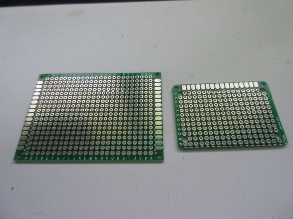
This part is up to you how you want to design your perfboard or you can follow the pictures for how I wired mine up. Basically sockets with adjacent headers and extra headers for connecting a programmer and power.
Before you start soldering pieces into place, drill 1/8″ holes the width and length of the standoffs. The length and width spacing are 25.4mm x 43.18mm, the mounting hole will line up with the holes on the perfboard. Test fit the holes with the four standoffs below the 30mm buttons.
Best to use IC sockets so that you can remove the chip if needed. I prefer the circular type sockets over the flat leaf type since they usually come in a strip that you can cut to size.
Use pin headers to make connecting your components easier should you need to replace them or incorrectly wire them up to the chip.
If you have space on your perfboard, put in headers to connect your programmer so that you can flash your chip if needed. The 2x3pins are for the ISP and the 2pins off to the side are for connecting power.
Note: Not shown in the pictures are extra pin headers for VCC and GND (pins 20 & 22) for the Wii cable to connect to. I only realized I needed the extra headers when I did the wiring.
Source: DIY NES Classic Advantage Controller
- What are the main advantages of this controller over stock options?
The controller offers an adjustable turbo function ranging from 1 to 35 presses per second and includes a Home Button to return to the NES Mini menu without pressing Reset. - Can I use an Arduino IDE to program the microcontroller?
Yes, you can use the Arduino IDE with an Arduino board, FTDI Programmer, or USBasp as a cheaper alternative to Atmel Studio. - Does the Atmega328P require an external crystal oscillator?
No, the fuse settings allow the chip to run on its internal 8MHz clock, so an external crystal is not needed. - How do I flash the fuses for the Atmega328P chip?
You must burn the fuses to L:0xE2, H:0xDE, and E:0xFD to ensure the chip does not run faster than 8MHz. - What voltage should be used to power the chip?
The chip must be powered externally with 3.3V because the Wii and NES Mini controllers operate at this voltage. - Which software options are available for programming the microcontroller?
You can use Atmel Studio, Arduino IDE, or WinAVR depending on your preferred toolchain. - Where can I find the CAD and STL files for the enclosure?
The CAD and STL files for the 3D printed enclosure are available on Thingiverse. - What type of switches should be used for the buttons?
You should use microswitches with strong springs to push up the Home, Select, and Start buttons effectively.