Summary of DIY – Waveform Generator using AVR Microcontroller
This article details the design of a waveform generator using an ATMega32 microcontroller and an 8-bit DAC0808. The system converts digital signals into analog waveforms like square, sine, triangular, staircase, and saw-tooth waves. A current-to-voltage converter utilizing an LM741 operational amplifier is employed to transform the DAC's current output into a usable voltage signal. The circuit is controlled via push buttons connected to PORTA, with digital outputs sent to PORTC.
Parts used in the Waveform Generator:
- AVR Development Board
- ADC – DAC card
- Digital Storage Oscilloscope (DSO)
- Power Supply
- Connecting Wires
- CRO Probes
- General purpose PCB
- AVR Microcontroller - ATMega32
- 8-bit - DAC0808
- Operational Amplifier – LM741
- Push Button Switches
- Resistors and Capacitors
To interface 8-bit DAC with AVR microcontroller ATMega32 and generate different waveforms like Square Wave, Sine Wave, Triangular Wave, Staircase Wave and Saw-tooth Wave.
Instruments
· AVR Development Board
· ADC – DAC card
· Digital Storage Oscilloscope (DSO)
· Power Supply
Apparatus
· Connecting Wires
· CRO Probes
· General purpose PCB
Components
· AVR Microcontroller – ATMega32
· 8-bit – DAC0808
· Operational Amplifier – LM741
· Push Button Switches
· Resistors and Capacitors
Theory
To generate different Analog waveforms using AVR microcontroller it is required to interface a DAC that will convert the Digital inputs given by microcontroller into corresponding Analog outputs and thus it generates different analog waveforms. The DAC output is current equivalent of digital input. So to convert it in to voltage a current to voltage converter is required. This current to voltage converter is build using Op-Amp LM741.
Circuit Description
PORTA is used as input and PORTC is used as output. Four push button switches are connected to PORTA pins PA0 to PA3. Rest four pins PA4 to PA7 are connected to Vcc. PORTC is connected to input pins A1 to A8 ofDAC0808. Vref pin of DAC0808 is connected to Vcc through 5 K Resistor to generate require output current Iref. –Vref pin is connected to ground through 5 K Resistor. The current output Iout of DAC0808 is connected to inverting input of Op-Amp LM741 that is used as current to voltage converter. A 5 K load Resistor is connected in the output of LM741 to generate voltage output.
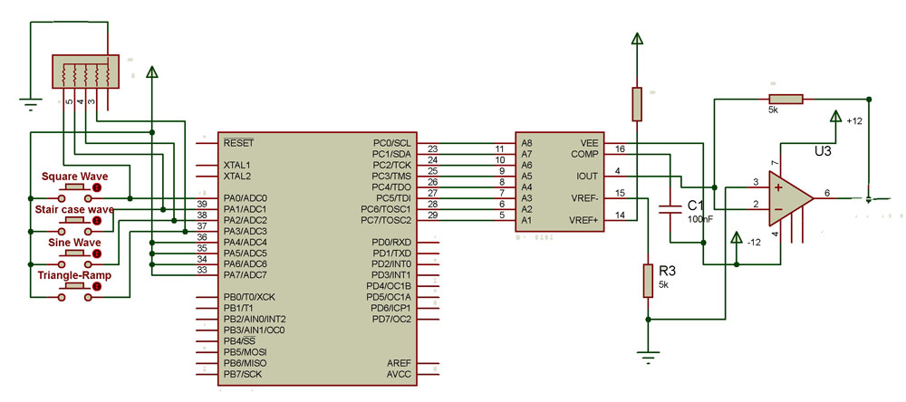
Complete circuit requires 3 different supplies +5 V, +12 V and -12 V. ATMega32 and DAC0808 require +5 V. DAC0808 require -12V for its Vee supply input. LM741 requires +12 V and -12 V for biasing. For detailed Circuit Diagram click on Circuit Diagram Tab
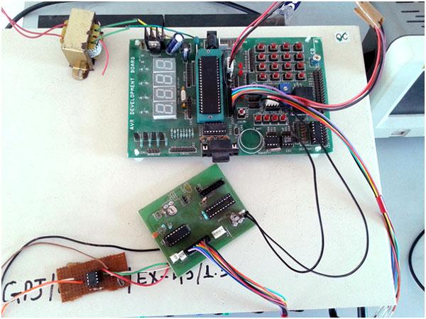
Here is the snap of circuit built using AVR Development Board, ADC-DAC card and Op-Amp
For more detail: DIY – Waveform Generator using AVR Microcontroller
- How are different waveforms generated?
Different analog waveforms are generated by interfacing a DAC that converts digital inputs from the microcontroller into corresponding analog outputs. - What component converts digital input to analog output?
The 8-bit DAC0808 converts the digital inputs given by the microcontroller into corresponding analog outputs. - Why is an Op-Amp required in this circuit?
An Op-Amp LM741 is used as a current to voltage converter because the DAC output is a current equivalent of the digital input. - Which ports are used for input and output?
PORTA is used as input and PORTC is used as output. - How are the push buttons connected?
Four push button switches are connected to PORTA pins PA0 to PA3. - What supplies are required for the complete circuit?
The circuit requires three different supplies: +5 V, +12 V, and -12 V. - How is the reference current Iref generated?
The Vref pin is connected to Vcc through a 5 K Resistor and the –Vref pin is connected to ground through a 5 K Resistor. - What generates the final voltage output?
A 5 K load Resistor connected in the output of the LM741 generates the voltage output. - Can this setup generate a Sine Wave?
Yes, the project can generate Square Wave, Sine Wave, Triangular Wave, Staircase Wave, and Saw-tooth Wave. - What happens if the circuit needs more detail?
For detailed information on the circuit diagram, one should click on the Circuit Diagram Tab.