Summary of Doppler Radar for Collision Avoidance
This project utilizes a Doppler radar array to detect movement, speed, and distance up to 25 feet, providing spatial awareness through vibration motors on the head, chest, neck, back, or arms. It includes an emergency mode for rapid threats and three operational modes controlled by a selector switch. The system is designed to enhance safety for pedestrians and individuals with sensory impairments without blocking their natural senses.
Parts used in Doppler Radar Safety System:
- Doppler radar sensors
- Vibration motors
- ATmega1284P microcontroller
- Band pass filter
- Comparator
- Motor driver circuit
- Mode selector push button
- Status indication LEDs
Introduction
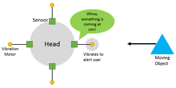
My project uses Doppler radar sensors in order to provide the user with movement, speed, and distance information of their environment. An array of Doppler radar sensors are placed on the user�s head and vibration motors are placed on the user�s chest, neck, back, and/or arms in order to provide input to the user without impeding any of their other senses. When something moves within about 25 feet of the user, the corresponding vibration motor for the particular direction relative to the user where the movement was detected will activate with a certain intensity to indicate how far away the movement was detected. In cases where an object is moving rapidly towards the user at a high speed, an emergency notification is sent such that all motors are activated and will pulse, while the motor corresponding with the direction the danger is in will be continuous and at a higher intensity to alert the user to where the danger is.
The reason for this project is that from looking at new safety features being implemented in cars such as forward collision warning, I found a great opportunity to use a similar technology to provide almost another sense for people that may be walking, bicycling, or otherwise. This project is intended to provide added safety to users in multiple situations. For example, this can provide added comfort and safety to users walking at night by alerting them towards anything they may not be able to see. In addition, when walking on the street, this can alert users of bicyclists or electric vehicles coming from behind that they might have not noticed. Lastly, this can also be used for those who have visual or audio impairment by provided extra information about their surroundings to improve their safety and comfort. For example, this project also allows users to be able to detect that they are walking towards an object like a wall, and can help avoid walking users from colliding into things.
High Level Design
Rationale
It is becoming increasingly interesting to have wearable technology, but one type, we have had for decades: technology to help the health and safety of people. This is just another kind of wearable device that can help many people in their daily lives. Inspired from safety technology in modern cars that car alert, and even prepare the car for dangers. One such system is the forward collisions warning or mitigating system that detect an imminent crash and can even help prevent it. With more and more people including wearable technology into their daily lives, this would be a great opportunity to integrate technology similar to the forward collision warning system, but for people. Not only would this device be useful to those with visual or audio impairments by providing almost another sensor to them, but also any other person in their daily lives. Walking at night can be uncomfortable and with very quiet hybrid and electric vehicles, it is difficult to sense the presence of them, which can lead to dangerous situations. This system helps provide extra information from every direction. However, we do not want to impede the user. For example, blind people heavily rely on their hearing to be able to understand their surroundings. This should not impair their hearing, perhaps by requiring their use headphones, as that takes away from their sense of their surroundings.
Background Information
The main piece of information required is that Doppler radar implements the Doppler shift effect. This means that the results we get are relative to the user. So, if the user is stationary and an object is coming towards the user, or if the object is stationary but the user to moving towards the object, we get, for all practical purposes, the same result.
��
Here, �is the original microwave frequency emitted by the sensor, which is at 10.525 GHz. Using the second equation as an approximation, the return frequency �is just a function of the original frequency and the relative velocity of the object. This is the fundamental property that allows both an object moving and the user moving to be essentially the same; thus enabling both collision avoidance and obstacle avoidance.
Logical Structure
Approaching the design of the project, it is important to first create an overall structure. For this project, there were two logical components: the sensor system, and the notification system. In addition, both of those systems are divided into the hardware and software systems. This division not only has helped in the process of developing, testing, and developing the project, but also modulizes the components so they could be upgraded or changed in the future. In real development, this modularity was actually kept up; for example, the vibration software is completely separate from the sensor software and, instead, provides an easy to use interface to the sensor software to control the vibration motors.

As shown in the figure above, the sensor provides an IF (intermediate frequency) signal to a band pass filter, which not only filters the frequency but also greatly amplifies the signal. The distance can actually be taken from the band pass filter, as it is just the voltage of the signal. The output of the band pass filter is also fed into a comparator, which outputs a 0-5V digital signal for movement changes. The higher the frequency of change, the faster the object is moving. These two signals are fed into the microcontroller, an ATmega1284P in this case. The sensor software measures the frequency using timers and distance using the ADC. It then determines the current situation and invokes vibration motor control functions. The software changes the PWM output for each of the vibration motors periodically using the input from the sensor software. The PWM drives a simple motor driver circuit and invokes the motor to vibrate. Each sensor has a corresponding vibration motor.
In addition to the core of the project, the extra piece is a mode selector. The mode controller�s hardware is composed of a push button and three differently colored LEDs for status indication. Pushing the button will cycle through the three different modes: normal mode, near distance mode, and emergency only mode. Each mode has a unique LED color to indicate to the user. This system simply adjusts the sensor software to only trigger the vibration software when certain conditions are met. This allows for more use scenarios as normal mode might be too informative in certain situations. For example, for most people, it is not an issue to be notified of every movement around them as they walk through a busy street; in this scenario, emergency only mode is much more appropriate as it will only alert them in dire situations.
Hardware and Software Tradeoffs
One of the major engineering decisions that need to be made is how much to do in hardware and how much to do in software. For this project, I opted to use each of their strengths as a basis of how I split apart the systems. In terms of signal filtering, I could have implemented it in both hardware and software. However, to be precise with the IF signal on the magnitude of millivolts, I would have needed much more than 10 bits of data from the internal ADC to be able to read the IF input. In addition, this imposes processing delay. Analog on the other hand was a much better choice because it is able to process it instantaneously for all practical uses and it was not limited by a finite resolution ADC. For the sensor information processing, software was an obvious choice. This can actually be implemented in digital hardware using basic logic gates, registers, and counters; however, the hardware would require too much space and would be difficult to change or upgrade.
There were also compromises required in order to produce manageable results. The sensor provided information from relatively large distances (about 25 ft.), permeates through many materials such as wood and some metal, and, with the high frequency of 10.525GHz, can detect very small movements as well. However, in order to actually make sense of the signal, it required a sensitive signal processing circuit which required a lot of calibration, a very consistent power source, and was fairly large. It would have been possible to use ultrasonic sensors with much less signal processing requirements; however, this greatly reduces resolution, permeability, and distance. For a system that should warn a user about an incoming collision, it is necessary to warn the user much earlier as it takes time for humans to respond, and ultrasonic would not have enough distance and resolution to provide the couple of seconds that people need to react.
Standards
As with any project, the IEEE Code of Ethics is always relevant. Being a relatively-long term project, it is always a good idea to be aware of the safety of others, good social conduct, and honesty. In addition, there are other standards to comply with is the frequency for the microwave sensor. The module complies with FCC rules, Part 15, Section 15.245, which talks about radiation emissions. In addition, falling under the �motion sensor� category, it must comply with the specified frequency for the US, which is 10.525 GHz. The specific module used compiles with both of the standards. The module is QC passed, so it has been verified to meet these standards. Lastly, I complied with the ISO C90 standard in which all variable declarations are done at the top of a function. This is done to follow convention and to allow anyone reading the code to be able to quickly reference the variable declarations in a consistent spot.
Intellectual Property
There have been some similar implementations as this; however, the form factors, interfaces, and technologies vary widely. Some such implementations include a single sensor in a cane to detect movement in front of the user, and a belt to detect movement around the user. However, none have referenced using Doppler radar or as many use cases as this project. For example, the cane can only sense ahead of the user, and is generally only useful for those who carry canes, and the belt would get a lot of user interfaces since the arms and hands tend to stay at about the waist level. In addition, none have reference multiple modes, or any user interface at all, include how they notify the user. Thus, I concluded there is no patents, trademarks, and copyrights relevant.
Hardware Design
The high level circuit diagram is included in the Appendix. Since the ATmega1284P only has 3 regular interrupt ports, I used the pin change interrupt ports instead. From the sensor system, the frequency outputs were connected to pin change interrupt ports. In order to help with both wire and software organization, two sensors were designated to port B pins and the other two to port D pins. The distance readings require the ADC, so they were all connected to port A pins. Lastly, the vibration motors PWM ports where attached to the PWM pins for the designated port. So the first two sensors (designated to port B) used B.3 and B.4 for the PWM and the other two (designated port D) used D.6 and D.7 for the PWM.
Sensor System
As previously mentioned, the sensor system requires a band pass filter and a comparator to output an analog signal for distance and a digital signal for frequency. Not only does this require frequency filtering and amplification, but also noise reduction. Since the IF signal shown below is just a few millivolts and very susceptible to noise, it is important to have a consistent circuit. Note that the signal almost consistently stays within a 20mV peak-to-peak and that moving something in front of the sensor causes only about 2mV difference in the signal. Also note the time base, with is 50ms per division. The signal is constantly changing, even at this fine granularity.
For more detail: Doppler Radar for Collision Avoidance
-
How does the system detect moving objects?
The system uses Doppler radar sensors that implement the Doppler shift effect to detect relative velocity between the user and objects. -
Can the device warn users of objects behind them?
Yes, an array of sensors is placed around the user so corresponding vibration motors activate based on the direction of detected movement. -
What happens when a high-speed object approaches rapidly?
All motors pulse while the motor corresponding to the danger direction activates continuously at higher intensity to signal an emergency. -
How many operational modes does the system have?
The system has three modes: normal mode, near distance mode, and emergency only mode. -
Why was analog hardware chosen over software for signal filtering?
Analog hardware was chosen because it processes millivolt signals instantaneously without the resolution limits or processing delays of an ADC. -
What frequency does the microwave sensor operate at?
The module operates at 10.525 GHz to comply with US motion sensor standards and FCC rules.