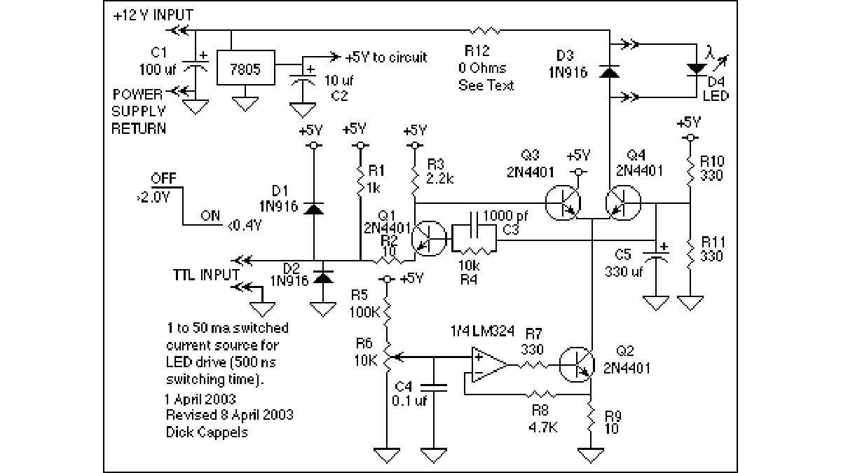
What it is
The circuit allows a precision regulated drive current to be set to drive an LED, and in response to a TTL level signal, the LED is switched on and off with rise and fall times of less than 500 nanoseconds and less than 7% overshoot. This was designed for biological experiments to study the photo repsonse of cone cells rabbit eyes. This circuit may also be useful in systems that require a stable pulsed light source, such as those that measures light transmission (turbidity and densitomitry insturments, for example) and for the transmission of low speed optical data (to 200 kHz). The components are all easy to obtain and low cost.
How it works
The circuit consists of an adjustable regulated current source (the op amp and Q2), a differential amplifier (Q3 and Q4) driven as a switch, and a level shifter (Q1) to shift the TTL input signal to levels necessary to drive the differential pair. The current from the current source is switched to either the +5 volt supply to the LED by the differential amplifier.
Current source (explained assuming the current is set to 50 ma):
The current source establishes the current that drives the LED. Voltage on the wiper of R6 is set to 0.5 volts, and this voltage is the reference for the op amp. By virtue of the feedback from the emitter of Q2, the op amp maintains 0.5 volts across R9, which is a 10 ohm resistor. The current through this resistor is 0.5V/10 ohms = 50 ma.
The emitter current is equal to the current through R9 because the op amp’s inverting input does not draw any appreciable current. Q1’s emitter current is shared between the base and collector of Q2, and because of Q2’s high current gain (greater than 100), more than 99% of the emitter current is passed to the collector, and this ratio is stable. Thus, the voltage set by R6 determines the collector current in Q2. The collector of Q2 is connected to the emitters of differential pair Q3 and Q4.
The 4.7k resistor, R8 is used to compensate for input bias drift. It is approximately equal to the resistance seen at the other op amp terminal.
C4 is to reduce the pickup of noise on the noninverting input of the op amp. On my breadboard, a couple of microseconds of ringing was seen on the output of the circuit until I put this capacitor in place. In your particular layout, you might need something like is for the inverting in put of the op amp. If you do, put a small capacitor across R8 instead of from the inverting input to ground because to put it to ground would induce a phase shift that could cause the circuit to oscillate.
Differential pair Q3 and Q4:
Transistors Q3 and Q4 are connected as an over-driven differential pair. The emitters are supplied current from Q2. Of the two transistors, the one with the highest base voltage will conduct all of the emitter current, which is equal to the collector current on Q2.
The all-or-nothing switching action results from the large difference in base voltages between the two transistors. When Q3 has the high base voltage, current from Q2’s collector goes to the +5 volt regulator. Q4 has the higher voltage, current from Q2’s collector goes through the LED then to the +12 volt power supply.
When the LED is off, Q3’s base is pulled to about +5 volts while the base of Q4 remains at +2.5 volts, which makes Q3’s emitter more positive than that of Q4, and so reverse biasing Q4’s emitter so it cannot draw any of the current from Q2.
When the LED is on, the base of Q3 is switched to less than 1 volt while the base of Q4 is kept at +2.5 volts, thus assuring that the emitter of Q3 is reverse biased and all the current from Q2 goes through the emitter (and therefore the collector) of Q4.
A small amount of the current from Q2 is used as base drive on Q3 (when Q3 is conducting) and Q4 (when Q4 is conducting). As is the case with Q2, this fraction of the total current is less than 1% of the total and is stable.
Voltage divider R10 and R11 create a 2.5 volt bias current for the base of Q4, while the voltage on the base of Q3 is switched by Q1 to well above and well below 2.5 volts. The 2.5 volt reference is also used to bias the base of the level shifter, Q1.
For more detail: FAST PRECISION LED DRIVER using microcontroller

