Summary of FM Radio Receiver Using Atmega644
This project designs a low-cost, user-friendly FM radio receiver using the ATmega644 microcontroller and an AIROHA AR1010 chip. The system tunes frequencies, scans for stations, stores favorites, and adjusts signal thresholds via a keypad, displaying status on an LCD. Although RBDS features were not implemented, the hardware supports future expansion.
Parts used in the FM Radio Receiver:
- AR1010, FM Single Chip Radio Receiver
- Breakout Board for AR1010
- STK500
- ATmega644
- White Boards
- Header Pins
- LCD, 16x2 Liquid Crystal Display
- Keypad
- 10KOhm Trimpots
- Audio Jack
- Other small parts (resistors, BJT, ect)
- TDA733N, RBDS Decoder
Introduction
The goal of our project was to design a low cost and user-friendly FM radio receiver.
Our project uses a FM receiver integrated circuit to perform the pre-processing units that are needed before the desired audio signals can be heard. The radio frequency is too fast for processing with our available hardware and the ATMega644. We integrated a LCD to communicate with the user and a keypad to allow the user to interact with the receiver and change stations. Our initial project idea was to create a receiver that could store audio, and later to design a radio that could create a playlist of the given radio station.
The song title information is sent along with the modulated audio signal through a system referred to as RBDS (Radio Broadcast Data System). Although we were unable to get the RBDS feature working, we have included some of the background, hardware, and software components in the RBDS section of the Appendix so that perhaps a future group can expand on our project to implement a feature using RBDS.
High Level Design
Background Information
FM (frequency modulated) radio signals are broadcasted on a carrier frequency within the range of 87.5MHz to 108.0MHz. Each station is provided 0.2MHz to broadcast their signal (in the United States), however, a maximum of .15MHz is typically used to prevent interference with adjacent channels. The incoming signal needs to first be demodulated, which involves multiple stages including the Low-Noise Amplifier, Frequency mixer, and other hardware-level FM signal processing units. We used an AIROHA AR1010 Single Chip FM Radio Receiver to perform these preprocessing stages for us.
It is worth mentioning at this point that we at times refer to the AR1010 FM Receiver and documents for the AR1000 receiver interchangeably. Both the AR1010 and AR1000 are receivers from AIROHA. The only difference between the two is that the AR1000 supports RBDS while the AR1010 does not. We were unable to obtain an AR1000 which would have been useful for the purposes of our project, but much of the supporting literature for our FM receiver design is specified for the AR1000.
Functionality
Our radio receiver can perform the following functions:
- Tune up or down a frequency
- Scan up or down for the next station with a strong signal
- Set up to 3 favorite stations which will be available later for quick tune
- Adjust the scanning threshold to pick up stronger or weaker stations
As mentioned, the United States separates frequencies by .2MHz (100.1, 100.3, 100.5 ect). However, in other regions of the word, the stations may be separated by only .1MHz. Therefore, to accommodate for both possibilities, we decided to allow the user to tune up or down by 0.1MHz increments.
The user controls the receiver through the keypad shown in the figure to the right. The buttons are mapped to the functionality as follows:
- 1, Tune up
- 2, Scan up
- 3, Increase scanning threshold
- 4, Tune down
- 5, Scan down
- 6, Decrease scanning threshold
- 9, Reset scanning threshold
- 0, Go to/ store favorite station 1
- F, Go to/ store favorite station 2
- E, Go to/ store favorite station 3
- D, Set favorite station
The rest of the buttons are not hooked up and pressing them will have no effect on the receiver. To set a favorite station, the user must perform the followings steps:
- Tune to the desired station
- Press the Set button (D)
- Press one of the favorite buttons (0, F, or E) in which the station will be stored. Any station previously stored at that button will be overwritten.
Overall Architecture
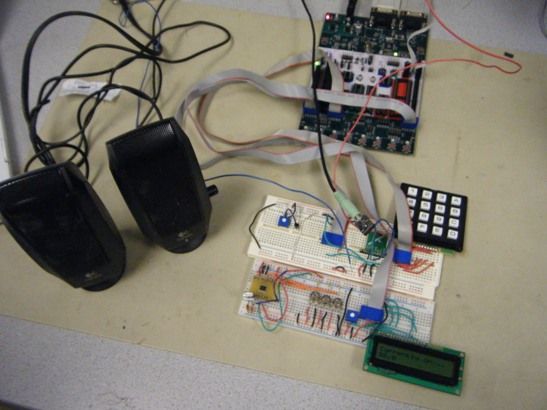
Our design can be broken into four main subcomponents: communication with the receiver, favorite station storage, the keypad, and the LCD. Although we were unable to incorporate the RBDS features into the final product, we also have included the work we have done with the hardware and software aspects that would support that additional functionality. These components and the communication between them is shown in the diagram below.
The incoming radio signal is transferred through the antenna to the AR1010 FM radio receiver. The breakout board with the receiver then processes the signal, and from that extracts the left and right outputs, which we connected to an audio jack. The user can simply plug in a speaker to hear the station. However, some type of amplifier is needed. Without one the output is not strong enough to be heard through headphones, even with the receiver set to full volume. Any button presses from the keypad get processed by the microcontroller, which will send the corresponding controls to the receiver and the appropriate message to the LCD.
Program/ Hardware Design
Software
Each of the four components of our design have software components: the communication with the AR1010 FM Receiver, interpreting button presses from the keypad, setting favorite stations in long-term memory, and displaying message on the LCD.
FM Receiver
We decided to the I2C protocol to communicate with the AR1010. The main reason we chose I2C over SPI was that the sample code available online used I2C. Also, the 3-Wire Interface used 26 clock signals to perform a simple write function, which would have complicated the SPI support on the ATmega644. Much of our code involving the I2C communication with the receiver was modified from the AR1000 ATMega168 Example Code available from Sparkfun Electronics.
We ran into significant difficulties with the I2C communication with the AR1010, the main issue was that a flag sent from the slave (AR1010) to the master (Mega644) was never being sent to signal that the start condition was received, and therefore the microcontroller was getting stuck in the wait state. We went through numerous other sets of sample code, including the one provided by request from NKC Electronics and tried to creat a program from scratch,incorporating information from the Programming Guide and the available code samples for the AR1010/AR1000.
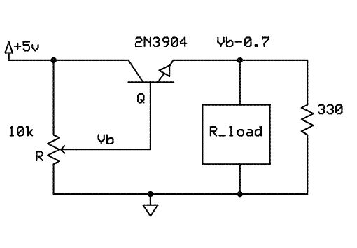
However, our problem persisted until we returned back to our original sample code. While we are still unsure why exactly the STC flag was not being set for the other codes, we have concluded that the initial attempt failed due to hardware errors, most likely a lack of pull-up resistors (discussed in the Hardware section below) on the data and clock line, which were remedied in our attempt to find a sequence of I2C commands that would work for our chip.
The registers on the AR1010 needed to first be initialized before any communication could follow. The values for the registers were recommended by the Programming Guide, and we determined that the Mega644 running on 16MHz did not require any modifications to these values. Once the AR1010 signaled that the registers had been written, we were able to begin communication.
All I2C functions were provided in the sample code, and also are modeled of the TWI protocols as provided in the Mega644 datasheet. The volume of the receiver is by default set to maximum, and as this still results in an output too quite to be heard on headphones, we did not feel the need to adjust the register determining the volume.
The receiver allows for easy and quick tuning to a given frequency. The channel of the receiver is stored in the second register. We chose to store the current frequency of the station in a global variable, as we wanted to be able to access the station we were listening to in other aspects of the program without having to read the register each time. The frequency will always have a minimum of one decimal place (in MHz) and will be between 87.5MHz (875KHz)and 108MHz (1808KHz), so storing the station in KHz allows the value to be represented with a 16 bit integer. The channel to be written to register 2 that corresponds to the given frequency can be calculated as follows:
RF Frequency (in KHz) = 690 + CHAN
This function was also provided by the Programming Guide. Once the new channel was written, a message was sent to the LCD to notify the user of the updated station. The tuning function takes in a simple value of 1 or 0 to determine whether or not the tuner should go up (1) or down (0).
The sample code also provided a function to allow for more dynamic tuning. The Tune Hi-Lo feature looks at the RSSI (register value reflecting signal strength) to help it fine tune the frequency. By testing this function, we did not notice a significant difference in the tuning, so decided to use the more direct method as previously described.
The main algorithm for scanning is outlined in the Programming Guide, and implemented in the sample code. Like the tuning function, the receiver can scan up or down, depending on the input parameter. In addition, the minimum strength of the radio station needed for the scan to halt on that particular frequency is dependent on a threshold value set in a register. We modified the code so that the user can increase, decrease, or reset the threshold to its original value. This way, should the user decide that the receiver is skipping over the stations that are still audible, maybe just not ideal, he or she can decrease the threshold through the changeThreshold function.
Parts List:
Parts List
| PART# AND DESCRIPTION | SOURCE | QUANTITY | COST/EACH | COST |
|---|---|---|---|---|
| Total | $50.24 | |||
| AR1010, FM Single Chip Radio Receiver | NKC Electronics | 1 | $0 | $0 |
| Breakout Board for AR1010 | NKC Electronics | 1 | $0 | $0 |
| STK500 | ECE 4760 Lab | 1 | $15 | $15 |
| ATmega644 | ECE 4760 | 1 | $8 | $8 |
| White Boards | ECE 4760 Lab | 2 | $6 | $12 |
| Header Pins | ECE 4760 Lab | 25 | $0.05 | $1.25 |
| LCD,16×2 Liquid Crystal Display | ECE 4760 Lab | 1 | $8 | $8 |
| Keypad | ECE 4760 Lab | 1 | $6 | $6 |
| 10KOhm Trimpots | ECE 4760 Lab | 5 | $0 | $0 |
| Audio Jack | ECE 4760 Lab | 1 | $0 | $0 |
| Other small parts (resistors, BJT, ect) | ECE 4760 Lab | – | $0 | $0 |
| (TDA733N, RBDS Decoder) | (STMicroelectronics) | (1) | ($0) | ($0) |
For more detail: FM Radio Receiver Using Atmega644
- What is the primary goal of this project?
The goal was to design a low cost and user-friendly FM radio receiver. - How does the user control the receiver?
The user controls the receiver through a keypad mapped to specific functions like tuning and scanning. - Can the radio store favorite stations?
Yes, the receiver can set up to 3 favorite stations which are available later for quick tune. - Does the system support RBDS features?
No, the team was unable to get the RBDS feature working in the final product. - What protocol is used for communication with the receiver?
The I2C protocol was chosen to communicate with the AR1010 FM Receiver. - Why was I2C selected over SPI?
I2C was chosen because sample code was available online and SPI would have complicated the support on the ATmega644. - How is the frequency stored in the program?
The current frequency is stored in a global variable as a value in KHz to allow representation with a 16 bit integer. - Can the scanning threshold be adjusted?
Yes, the user can increase, decrease, or reset the scanning threshold to pick up stronger or weaker stations.