Summary of Getting Started with Assembly Programming for ATMELAVRMicrocontrollers
Learning assembler offers control, speed, compact code, and clear timing for time-critical or memory-limited applications. AVR (AT90S/AT90S2313) chips and ISP programming simplify development and testing. Use simple experimental hardware or commercial boards (STK500) and ATMEL Studio for simulation, single-stepping, register and I/O inspection, and quick in-circuit programming via ISP6/ISP10. Start small, keep subroutines, and iterate with diagnostic lines; assembler learning is straightforward with hands-on testing.
Parts used in the AVR Assembler Programming Project:
- AT90S2313 microcontroller (or AT90Sxxxx family)
- AC transformer
- 5V/1A voltage regulator
- XTAL clock crystal (10 MHz suggested)
- Reset components (reset circuit parts)
- ISP10PIN connector (or ISP6PIN connector)
- Resistors (for LEDs and I/O protection)
- LEDs (for output indication and programmer status)
- Programming adapter for PC parallel port (or commercial programmer)
- STK500 commercial programming board (optional)
- Connecting wires and common ground
Why learning Assembler?
To use assembler or opt for alternative programming languages, that’s the dilemma. What’s the rationale behind acquiring proficiency in another language when I’ve already grasped different programming languages? The strongest case for this: residing in France, you might manage with English, yet you’ll never truly assimilate or feel entirely comfortable, leaving life needlessly complex. While it might suffice, it’s not quite fitting. When urgency demands, resorting to the native language becomes imperative.
Short and easy
Assembler commands are translated individually into executed machine commands. The processor solely executes the intended instructions and performs the essential tasks without additional loops or unnecessary features, preventing bloating of the generated code. Opting for assembly language becomes paramount when program storage is constrained and limited, necessitating program optimization to fit into memory. It offers the advantage of producing shorter programs that are easier to debug, as each step retains a clear and logical significance.
Fast and quick
As assembly language executes only essential code steps, it maximizes program speed by performing only necessary operations. Every step’s duration is precisely known, making it crucial for time-sensitive applications such as precise time measurements when a hardware timer is unavailable. Opting for assembly becomes imperative for achieving excellent performance in these cases. However, if time is not a critical factor and operating mostly in a wait state (99% inactive), any programming language can be chosen without much concern.
Assembler is easy to learn
As assembly language executes only essential code steps, it maximizes program speed by performing only necessary operations. Every step’s duration is precisely known, making it crucial for time-sensitive applications such as precise time measurements when a hardware timer is unavailable. Opting for assembly becomes imperative for achieving excellent performance in these cases. However, if time is not a critical factor and operating mostly in a wait state (99% inactive), any programming language can be chosen without much concern.
AT90Sxxxx are ideal for learning assembler
Assembler programs exhibit a unique characteristic: the chip dutifully executes commands without questioning, operating according to your instructions without raising concerns about overwriting or confirming actions. In this realm, all protections necessitated must be manually programmed by the user, as the chip complies precisely with its directives. There exists no preemptive warning unless foreseen and coded beforehand.
Debugging fundamental design flaws is just as intricate in assembler as it is in any other programming language. However, when it comes to testing programs on ATMEL chips, the process is notably straightforward. If the program fails to perform as anticipated, incorporating diagnostic lines into the code, reprogramming the chip, and conducting tests becomes a hassle-free task. This method bids farewell to the days of EPROM programming, the hassle of UV lamps to erase test programs, and the frustration of pins that no longer fit into sockets after numerous insertions and removals.
Changes can now be swiftly programmed, compiled efficiently, and either simulated within the studio environment or validated in-circuit. This streamlined approach eliminates the need for pin removal and the unpredictable failure of UV lamps, ensuring that your creative solutions for resolving bugs are not hindered by hardware issues.
Test it!
Take your time as you embark on your initial strides! If you’re acquainted with another (higher-level) programming language, it’s best to set it aside initially. Every assembly language is rooted in specific hardware principles. Many attributes distinctive to other programming languages lack relevance in assembly.
The first five directives might pose challenges in comprehension, but once grasped, your pace of learning accelerates rapidly. Once you’ve written your initial lines of code, consider accessing the instruction set list, then relax in a moment of contemplation, pondering the nature of all the other commands.
Avoid attempting to code for a complex machine right from the start. This approach holds no merit in any programming language and only leads to frustration.
Annotate your subroutines and archive them in a designated directory. Once debugged, you’ll inevitably require them again within a short interval.
Wishing you success in your endeavors!
Hardware for AVR Assembler Programming
Acquiring proficiency in assembler necessitates basic hardware tools to verify program functionality in real-world scenarios. In this segment, two straightforward schematics are presented, facilitating the creation of essential hardware and providing key insights into the foundational background needed. Constructing this hardware is notably straightforward; I can confidently say there’s hardly an easier method to validate your initial software endeavors. Moreover, for those inclined towards further experimentation, leaving room for future expansions on your experimental board is advisable.
If soldering isn’t your preference, pre-assembled boards are available for purchase as well. The characteristics of these ready-to-use boards are detailed in the subsequent section.
The ISP Interface of the AVR processor family
Before delving into practical application, it’s essential to grasp the fundamentals of the serial programming mode within the AVR family. Contrary to misconceptions, programming and reading an AVR flash memory doesn’t require three distinct voltages. There’s no necessity for an additional microprocessor solely for AVR programming, nor do you need an extensive 10 I/O line setup to convey instructions to the chip. Moreover, removing the AVR from your experimental board prior to programming isn’t a requisite. In fact, it’s even simpler than these assumptions.
All these functions are facilitated by a built-in interface embedded within the AVR chip. This interface facilitates the writing and reading of content from the program flash and the integrated EEPROM. This interface operates serially and relies on three primary signal lines:
– SCK: Serving as a clock signal, it handles the shifting of bits meant for writing into the memory by utilizing an internal shift register. Additionally, it manages the shifting out of bits intended for reading from another internal shift register.
– MOSI: This signal functions as the data carrier, sending the bits intended for writing to the AVR.
– MISO: Operating as the data receiver, it gathers the bits read from the AVR.
These three signal pins establish an internal connection with the programming machinery only when you set the RESET pin (sometimes referred to as RST or restart) to zero. In normal AVR operation, these pins function as programmable I/O lines, similar to all the others.
Should you intend to utilize these pins for different functions during standard operation and in-system programming, it’s crucial to ensure that these two uses don’t clash. Typically, this requires separating them using resistors or employing a multiplexer. The specific actions needed in your scenario will be contingent upon how you use the pins during normal operation. If you can exclusively allocate them for in-system programming, consider yourself fortunate.
While not obligatory, it is advisable for in-system programming to power the programming hardware from your system’s supply voltage. This simplifies the process and necessitates two extra lines between the programmer and the AVR board. GND serves as the shared ground, while VTG (target voltage) represents the supply voltage, typically at 5.0 volts. This totals to 6 lines connecting the programmer and the AVR board. The resulting ISP6 connection, as outlined by ATMEL, is depicted on the left side.
There are always alternative standards that existed prior within established norms. This forms the technical foundation underpinning the adapter industry. In our scenario, the previous alternative standard, known as ISP10, was specifically devised and utilized on the STK200 board. Remarkably, ISP10 remains extensively prevalent, even persisting in the setup of the STK500. ISP10 features an extra signal dedicated to powering a red LED, serving as an indicator that the programmer is functioning. This inclusion represents a practical concept. Simply connect the LED to a resistor and secure it to the positive supply voltage for operation.
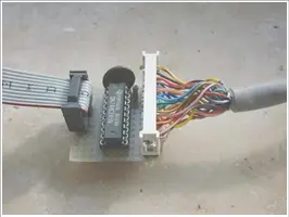
Programmer for the PC Parallel Port
There are always alternative standards that existed prior within established norms. This forms the technical foundation underpinning the adapter industry. In our scenario, the previous alternative standard, known as ISP10, was specifically devised and utilized on the STK200 board. Remarkably, ISP10 remains extensively prevalent, even persisting in the setup of the STK500. ISP10 features an extra signal dedicated to powering a red LED, serving as an indicator that the programmer is functioning. This inclusion represents a practical concept. Simply connect the LED to a resistor and secure it to the positive supply voltage for operation.
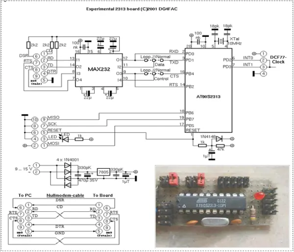
Experimental board with a AT90S2313
For experimental testing purposes, we utilize an AT90S2313 microcontroller on an experimental board. The schematic illustrates:
– A small voltage supply connected to an AC transformer and a 5V/1A voltage regulator.
– An XTAL clock generator (operating at 10 MHz, although frequencies below the maximum for the 2313 will also function).
– Components essential for a reliable reset mechanism during voltage supply switching.
– The ISP-Programming-Interface equipped with an ISP10PIN-connector.
These components serve as the foundation for getting started. To expand functionality, you can connect additional peripheral add-ons to the numerous available I/O pins of the 2313.
One of the simplest output devices to integrate is an LED connected, via a resistor, to the positive supply voltage. This setup enables you to initiate your initial assembler program, allowing you to control the LED by switching it on and off.
Ready to use commercial programming boards for the AVR family
If you prefer not to build your hardware and have some extra funds at your disposal, you have the option to invest in a commercial programming board. An easily accessible choice is the STK500 (for instance, available from ATMEL), which offers the following hardware features:
– Slots for programming a majority of the AVR types
– Both serial and parallel programming capabilities
– ISP6PIN and ISP10PIN connectors for external In-System-Programming
– Adjustable oscillator frequency and supply voltages
– Incorporation of plug-in switches and LEDs
– An RS232C-connector (UART) ready to be connected
– A serial Flash-EEPROM
– Access to all ports via a 10-pin connector
Getting started with experiments can be initiated using the included AT90S8515. This board connects to the PC through a serial port (COMx) and can be managed by later versions of AVR Studio, which can be obtained from ATMEL’s website. This setup fulfills all the necessary hardware requirements that a beginner might have.
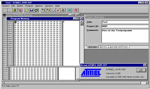
Programming the chips
To facilitate programming our hex code onto the AVR, ATMEL previously developed the ISP software package. (Note that this software is no longer supported or distributed.) To begin the process, we launch the ISP software and load the hex file we’ve just generated, typically by selecting the “LOAD PROGRAM” option from the menu. This action appears as follows:
Utilizing the “PROGRAM” menu option will write our code into the chip’s program memory. Several prerequisites must be met for this process to succeed (selecting the correct parallel port, connecting the programming adapter, ensuring the chip is on the adapter, powering the setup, etc.).
In addition to the ATMEL-ISP and the programming boards, other programming boards or adapters can be employed, along with suitable programming software. Various alternatives to these are accessible on the internet.
Simulation in the studio
At times, despite error-free assembly and successful compilation, self-authored assembly code might not perform as expected once programmed onto the chip. Evaluating the software directly on the chip can be challenging, especially when operating with minimal hardware and lacking the ability to display interim outcomes or debugging signals. In such scenarios, the ATMEL studio offers optimal debugging options. It enables testing of the software or its segments, allowing for step-by-step evaluation and display of results.
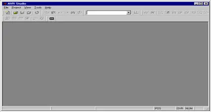
The studio has commenced, and here’s how it appears initially. We begin by accessing a file through the menu item labeled “FILE OPEN.” For illustration purposes, we’ll use the tutorial file named test1.asm, as it contains additional commands and actions beyond our previous single-command program.
Access the file TEST1.OBJ generated after assembling TEST1.asm. You’ll be prompted to choose preferred options (if necessary, alterations can be made via the SIMULATOR OPTIONS menu item). The designated options will include:
Within the device selection segment, choose the specific chip type you require. For accurate simulation timings, ensure the correct frequency is selected.
To access the content within specific registers and ascertain the processor’s status, we opt for the “VIEW PROCESSOR” and “REGISTERS” options. Subsequently, the display will reflect the following format.
The processor window exhibits various values such as the command counter, flags, and timing details (e.g., a 1 MHz clock). The stopwatch feature allows measuring the time required for executing routines and similar tasks.
We’re commencing the program execution now. Opting for the single-step method (TRACE INTO or F11), we refrain from using GO to avoid continuous execution, which wouldn’t provide much visibility due to the simulation’s high speed. After the initial step is executed, the processor window is anticipated to exhibit the following attributes.
The program counter marks step 1, with the cycle counter indicating 2 (as RJMP required two cycles). Given a clock speed of 1 MHz, two microseconds have transpired, and there have been no alterations observed in the flags and pointer registers. Concurrently, the source text window shows a pointer positioned on the upcoming command scheduled for execution.
Pressing F11 once more initiates the execution of the subsequent command, leading to the setting of register mp (equivalent to R16) to 0xFF. Consequently, this change should be highlighted within the register window.
The updated value of Register R16 is showcased in red text format. It’s worth noting that we have the flexibility to modify the register’s value at any given moment, allowing us to test the ensuing outcomes.
Moving forward, we proceed to execute step 3, which involves outputting to the direction register of Port B. To visualize this action, we initiate the opening of a fresh I/O view window and proceed to select Port B. This selection within the display is anticipated to resemble the following layout.
In the I/O-view window of Port B, the Data Direction Register currently reflects the updated value. Should it be necessary, the values can be manually altered, allowing for individual pin modifications if desired.
- Why learn assembler instead of a higher-level language?
Assembler produces shorter, faster programs with precise timing and smaller memory footprint, important for constrained or time-critical applications. - Are AT90Sxxxx chips good for learning assembler?
Yes, AT90Sxxxx chips are ideal for learning because they execute instructions exactly and support easy in-circuit testing without EPROM hassles. - What signals does the AVR ISP interface use?
The ISP interface uses SCK (clock), MOSI (data to AVR), and MISO (data from AVR), plus RESET to enable programming. - Do I need to remove the AVR from the board to program it?
No, in-system programming allows programming the AVR without removing it from the experimental board. - What additional lines are recommended for in-system programming?
It is recommended to include GND and VTG (target voltage) so the programmer can be powered from the system supply, totaling six lines for ISP6. - Can I use commercial programming boards instead of building hardware?
Yes, commercial boards like the STK500 provide slots for many AVR types, ISP connectors, adjustable clock and supply, switches, LEDs, and other features for beginners. - How do I program the chip with ATMEL software?
Use the ISP software to load the hex file via Load Program and then choose Program, ensuring correct port, adapter connection, chip placement, and power. - How can I debug assembly code without full hardware?
Use ATMEL Studio simulation to single-step code, view processor registers, flags, I/O ports, and measure timing for debugging. - What initial hardware is suggested for experiments with AT90S2313?
A small power supply with a 5V regulator, XTAL clock, reset circuit, ISP connector, and simple outputs like an LED on an I/O pin are suggested. - What is a good practice when starting with assembler?
Start small, set aside higher-level language habits, annotate and archive debugged subroutines, and use diagnostic lines while testing.