Summary of Getting Started With Atmel AVR and BASCOM
This article guides beginners from scratch to building a microcontroller circuit using an Atmel Tiny-26 chip. It details constructing a 5V power supply from a 9V battery, utilizing a 7805 regulator and capacitors for stability. The guide explains wiring techniques with solid wire, calculating resistor values to protect LEDs, and verifying the circuit's functionality.
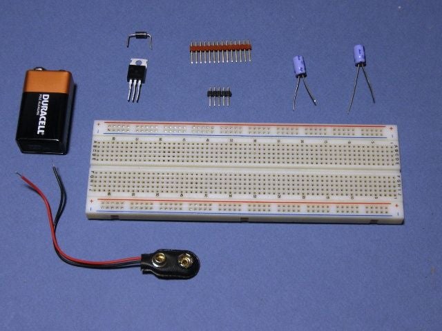
Parts used in the Microcontroller Circuit Project:
- Breadboard (medium sized)
- Atmel Tiny-26 microprocessor
- 9 volt battery
- 7805 voltage regulator
- Diode
- SIP header (Single Inline Pins)
- Capacitors (47uF, rated at least 6 volts)
- LEDs
- Resistors (150 ohms)
- 22 to 24 gauge solid wire
I have seen plenty of Instructables showing how to work with microprocessors, but they all assume that you have worked with them before and know what you are doing. I have not seen an Instructable that takes you from nothing and builds on each step.
What we will do here is to start with a bare breadboard and build each connection and each component until we have everything we need to program a microcontroller to do something. In this Instructable we will blink some LEDs in sequence… then if you build this circuit… your first project can be to change the code slightly to make it into a traffic light.
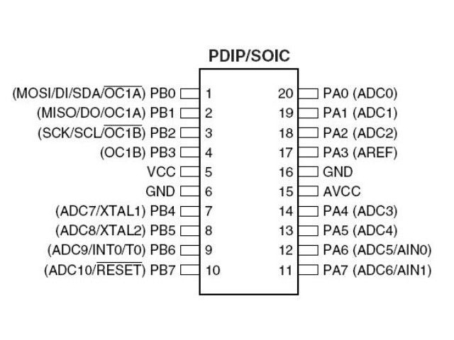
I picked an older Atmel chip, the Tiny-26 to get started. It is a smaller microprocessor, very inexpensive, and easy to understand. Once you understand what we are doing here, you may want to try a more powerful chip like the Mega-328P which has more pins and more memory.
Note: The Tiny-261, Tiny-461, and Tiny-861 are pin compatible newer versions of the Tiny-26. They have 2K, 4K, and 8K of memory. If used, simply change the header by selecting the appropriate chip and recompile the program to use the newer version. The new chips have more functions that can be assigned to each pin. See the datasheets for more details.
Tiny 261, 461, 861 Datasheet (PDF)
Tiny 26Datasheet (PDF)
Below is an image with the pins for the chip we will be using… we will be connecting the power and ground… in this case 5v. So where do we get 5 volts? We will build a power supply from a 9v battery.
Let’s get started!
Video posted in a larger size at: http://www.youtube.com/watch?v=Jxica6Yenh8
Step 1: Breadboards and Building Circuits.
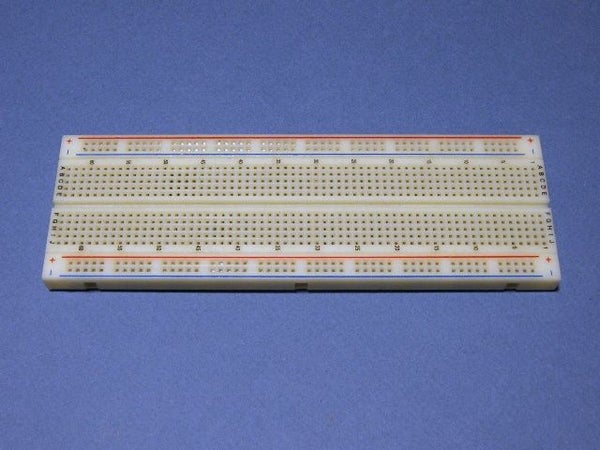
Below you can see a breadboard… they come in many sizes depending on how complex the circuit you want to build will be. We will use a medium sized breadboard with enough room for our power supply, the microprocessor, and the LEDs we want to control.
Step 2: Starting With the Power Supply
We will use a voltage regulator called a 7805. It has three pins, the first is the input, next is the ground, and last is the output voltage… in this case 5 volts. The chip needs to have greater than 6 volts to be able to regulate it down to 5 volts… but it cannot have more than 36 volts. The 9 volt battery works well in this application.
We also want to install a diode into the circuit… it will allow current to flow in only one direction. The reason we install it is so that if we connect the battery backwards it will not let the current flow and will protect our circuit from damage. The diode has a line printed on it, this should be on the most negative side, in our case… it connects to the input of the voltage regulator.
The 9 volt battery clip uses stranded wires… they do not plug into a breadboard very well so we need to make it so that we can install the connections properly. We will use what is called a SIP header. (Single Inline Pins) The wires are soldered to the pins and then can be inserted into the breadboard.
If you look at image #3, you can see that the wires are soldered to TWO pins. This is done to provide a stronger connection that won’t turn or jiggle loose. (It’s a good tip to remember! )
We insert the pins into the breadboard and install the diode. (Image #4)
In Image #5 you can see that we have added a capacitor… it is a 47uF rated at least 6 volts… these are 25 volts… so they are fine. They act to smooth out the voltage when things like LEDs turn on and off. One way to think of them is like the water tank in your toilet… when you flush you need a large flow of water all at once… but the supply line is very small. The tank holds enough water to even out the flow. Likewise, the capacitor holds extra power for when there is a surge from things starting and stopping.
One capacitor goes between the input to the voltage regulator and the ground, the other goes between the ground and the regulated 5 volts. The capacitor has a marking to show which side connects to ground.
In Image #6 and Image #7 you can see the completed power supply.
Step 3: Wires and Connections
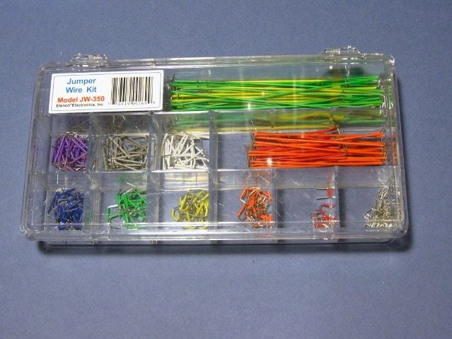
You will notice that my connections to the board are very neat and easy to follow. (At least I hope so!) I am using a wire kit that is available online from several places. The kits are about $10 to $20 depending where you look… and refills are available from places like Digikey .
The kits make your wire connections short, clean, and easy to follow when you come back to them in the future. The refills are a bit pricey, but if you get into electronics quite a bit you will find that you don’t want to live without them.
A great way to get started is to find some 22 gauge to 24 gauge SOLID wire. You don’t want stranded wires in a breadboard… they just don’t work well. Solid wire is useful when you want it stiff and bendable as we are doing here. Stranded wire is used when it must be flexible.
If you see the local telephone repair person ask if they have any scrap 25 pair cable. They often get it in 500 foot rolls… and if it has less than 20 or so feet will often throw it away. The cable has a string that when pulled will cut the jacket and give you a whole bunch of wires as shown in Image #3 .
Step 4: How Do We Know If It’s Working???
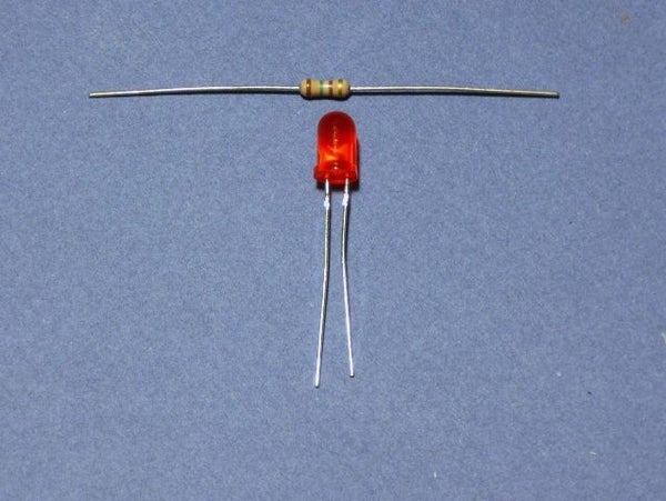
So now we have a power supply for the microprocessor and out LEDs. But how do we know if it is working? We can install an LED so that when the power supply is on it will illuminate. This is also a good time to teach you about resistors. We will be working with 5 volts… but an LED is designed to run on only 2 volts. (Approximate, they vary depending on the type. )
If we were to connect a 2v LED to the 5v supply, it would get very bright for a very short period of time… then POOF! Here is where you need a little math… don’t worry… it’s not too bad.
If we look at the specification sheet for the LED, it says that it runs on 2 volts at 20mA. Okay… let’s start with the voltage… 5 volts minus 2 volts is 3 volts. So we have 3 volts too much for the LED. (Told you the math wasn’t too hard.)
Okay… the LED runs on 20mA… that’s the same as 0.020 amps. (mA are 1/1000 of an amp… so 1000mA = 1A) We know that we have 3 volts too much… so divide that by the current that the LED is supposed to run at… 3 divided by 0.020 = 150.
So we know that we need to have a resistance of 150 ohms to slow down the flow of electricity to a point where it won’t burn out the led. Voltage / Current = Ohms.
We install our resistor (150 ohms) and our LED onto the board… now we know if we have power or not!
Source: Getting Started With Atmel AVR and BASCOM
- What microprocessor is recommended for beginners?
The article recommends the older Atmel Tiny-26 because it is small, inexpensive, and easy to understand. - How do you get 5 volts for the circuit?
You build a power supply using a 9 volt battery connected to a 7805 voltage regulator. - Why is a diode installed in the power supply?
The diode allows current to flow in only one direction to protect the circuit if the battery is connected backwards. - What is the purpose of the capacitors in this project?
The capacitors smooth out the voltage when components like LEDs turn on and off by holding extra power during surges. - What type of wire should be used in a breadboard?
You should use 22 to 24 gauge solid wire because stranded wires do not work well in breadboards. - How do you calculate the correct resistor value for an LED?
Subtract the LED voltage from the supply voltage, then divide that result by the current in amps to find the resistance in ohms. - Can newer chips replace the Tiny-26?
Yes, the Tiny-261, Tiny-461, and Tiny-861 are pin-compatible newer versions with more memory and functions. - How can you verify if the power supply is working?
You can install an LED with a resistor; if it illuminates, the power supply is functioning correctly.