Summary of Getting Started with C Programming for the ATMEL AVR Microcontrollers
This tutorial introduces C programming for Atmel AVR microcontrollers using Atmel Studio and the ATmega16 on an STK500 board. It covers installing Atmel Studio, creating a GCC C project, compiling to a HEX file, source-level debugging with the simulator, and downloading/running the HEX on the STK500 with hardware jumper and serial setup. The example toggles one of eight LEDs via switches on the board. Step-by-step instructions and screenshots guide project setup, debugging views, and programming the device via ISP.
Parts used in the led Project:
- Atmel Studio 6 (software)
- Microsoft Visual Studio 10 Service Pack 1 (software prerequisite)
- STK500 development board
- ATmega16 microcontroller
- SPROG3 to ISP6PIN cable/jumper
- Serial cable (RS232) for STK500 RS232 CTRL connector
- SWITCHES jumper (to PORTA)
- LEDS jumper (to PORTB)
- 12V DC power supply
- HEX file produced by Atmel Studio (led.hex)
Introduction
This tutorial provides information on the tool and the basic steps for programming the Atmel AVR microcontrollers using C. It is aimed at people who are new to this family of microcontrollers. The Atmel STK500 development board and the ATmega16 chip are used in this tutorial; however, it is easy to adopt the information given here for other AVR chips.
Installing tool for C programming
To program Atmel AVR microcontrollers using C, you will need Atmel Studio software, which is freely available from the company website. Atmel Studio is an integrated development environment that includes the editor, C compiler, assembler, HEX file downloader, and a microcontroller emulator.
To install Atmel Studio, perform the following steps: Download setup files for Atmel Studio 6 from ATMEL (about 820MB) http://www.atmel.com/microsite/atmel_studio6/ Download Microsoft Visual Studio 10 Service Pack 1 from Microsoft (about 1.6GB):http://www.microsoft.com/en-us/download/details.aspx?id=23691 Run the setup file for Atmel Studio 6. Accept the default options. Run the setup file for Microsoft Visual Studio 10 Service Pack 1. Accept the default options.
Using Atmel Studio for C programming
As an example, we will create a simple C program for the Atmel AVR that allows the user to turn on one of the eight Light Emitting Diodes (LEDs) on the STK500 development board, by pressing a switch. Next, you will be guided through four major stages:
- creating an Atmel Studio project,
- compiling C code to produce a HEX file,
- debugging C program using the simulator,
- downloading HEX file to the STK500 development board and running it.
3.1 Creating an Atmel Studio project Perform the following steps to create a simple Atmel Studio project.
Start the Atmel Studio 6 program by clicking its icon on the Windows Desktop
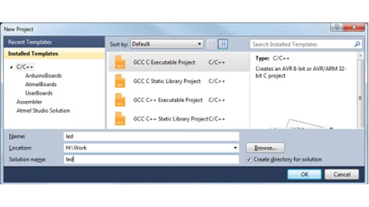
- Select menu File | New Project. In the dialog box that appears (see Figure 1), select
- ‘GCC C Executable Project’, and specify the project name and project location.
- Select the option ‘Create directory for solution’ so that a folder will be created to
- store. In this case, we use ‘led’ as both the project name and the solution name1
- .
- Click button OK
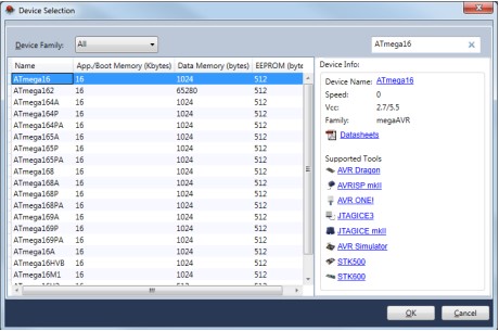
In the ‘Device Selection’ dialog that appears (see Figure 2), search for ATmega16 and then click button OK Note: If you want to use other AVR chips such as ATMAGE8515, select it at this step. In this tutorial, we will use ATMEGA16 for both software simulation and hardware testing.
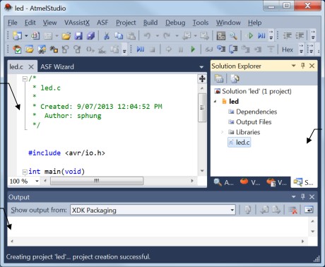
• A project file will be created and Atmel Studio displays an initial file led.c (see Figure 3).
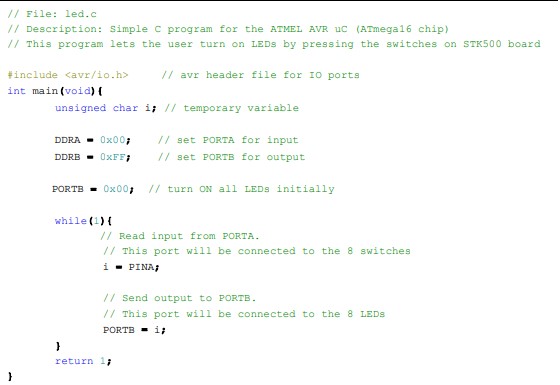
Enter the C code shown in Figure 4. It is not important to understand the code at this stage, but you can do that by reading the C comments. Click menu File | Save All to save all project files. Note that an Atmel Studio solution has extension ‘.atsln’; an Atmel Studio C project has extension ‘.cproj’.
3.2 Compiling C code to HEX file
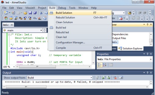
- Click menu Build | Build Solution to compile the C code (the hot-key for this is F7).
- If there is no error message, a file called led.hex will be produced (see Figure 5). This file contains the machine code that is ready to be downloaded to the ATmega16 microcontroller. The file is stored in sub-folder ‘debug’ or ‘release’ of your project.
- If there are error messages, check your C code. Most often, error messages are caused by typographical or syntax errors. Atmel Studio will show the line numbers where errors appear in the C code.
3.3 Debugging C program using the simulator
Debugging is an essential aspect in any type of programming. This section will show you how to debug a C program at source-code level, using Atmel Studio. Basically, you can execute a C program one line at a time, and observe the effects on the CPU registers, IO ports, and memory. This is possible because Atmel Studio provides a software simulator for many AVR microcontrollers, including the ATmega16 chip. The following steps in this section do not require a STK500 board.
We will continue with the example project led.cproj created in Section 3.2 of this tutorial.
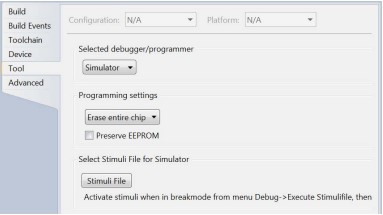
Start the debugger by selecting menu Debug | Start Debugging and Break. Atmel Studio will require you to specify a debugger. Select ‘Simulator’, as shown in Figure 6.
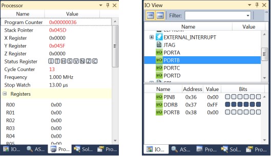
Atmel Studio lets you examine the contents of CPU registers and IO ports. To enable these views, select menu Debug | Windows and then Processor View or I/O View. Refer to Figure 7.
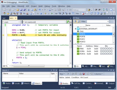
A yellow arrow will appear in the code window (Figure 8); it indicates the C instruction to be executed next.
Select menu Debug | Step Into (or press hot-key F11) to execute the C instruction at the yellow arrow. Figure 7b shows the IO view after the following C instruction is executed:
DDRB = 0xFF; // set PORTB for output
Note that Port B Data Direction Register (DDRB) has been changed to 0xFF.
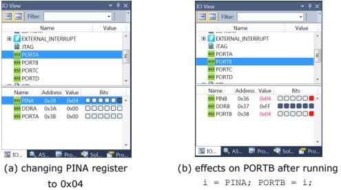
While debugging the C program, you can change the contents of a register. For example, to change Port A Input Pins register (PINA), click on the value column of PINA and enter a new value (Figure 9a). This change will take effect immediately. Subsequently, the contents of PORTB will be 0x04 (see Figure 9b) after running the
two C instructions:
i = PINA;
PORTB = i;
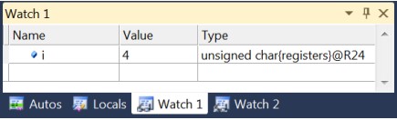
To monitor a C variable, select the variable name in the code window, click menu Debug | Quick Watch, and then click button Add Watch. The variable will be added to a watch window, as in Figure 10.
The Debug menu provides many other debugging options, such as running up to a break point, or stepping over a function or a loop. To view the assembly code along with the C code, select menu Debug | Windows | Disassembly. To stop debugging, select menu Debug | Stop Debugging.
3.4 Downloading and running HEX file on AVR board
To perform the steps in this section, you will need an STK500 development board from Atmel and the ATmega16 chip. The ATMEGA16 should be placed in socket SCKT3100A3. Note: If you use other AVR chips such as ATMEGA128, refer to Table 3.2 AVR Sockets, ‘AVR STK500 User Guide’ for the exact socket.
Hardware setup
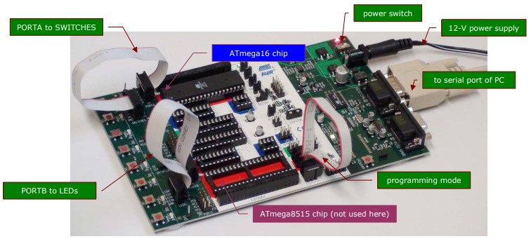
Refer to Figure 11 when carrying out the following steps.
Step 1: Connect the SPROG3 jumper to the ISP6PIN jumper, using the supplied cable
in the STK500 kit. This step is needed to program the ATmega16 chip.
• Step 2: Connect the board with the PC using a serial cable. Note that the STK500 has two RS232 connectors; we use only the connector marked with RS232 CTRL.
• Step 3: Connect the SWITCHES jumper to PORTA jumper. This step is needed in our example because we want to connect 8 switches on the development board to port A of the microcontroller.
• Step 4: Connect the LEDS jumper to PORTB jumper. This step is needed in our example because we want to connect 8 LEDs on the development board to port B of the microcontroller.
• Step 5: Connect the board with 12V DC power supply and turn the power switch ON. All testing involving the ATmega16 chip require Steps 1, 2, and 5. Steps 3 and 4 are needed only for this particular example.
Downloading and running HEX file
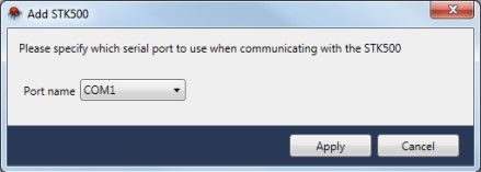
• In Atmel Studio, select menu Tools | Add STK5002.
• In the ‘Add STK500’ dialog box that appears (see Figure 12), select the correct serial
port and click button ‘Apply’.
- For your home PC with inbuilt serial port, the serial port is usually COM1.
- For a computer using a USB-to-Serial cable, the serial port can be a different number.
- For computers in SECTE Digital Lab 35.129, the serial port is COM5 or COM4.
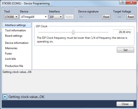
In the ‘Device Programming’ dialog box that appears (see Figure 13), select ‘Tool’ = STK500, ‘Device’ = ATmega16, and ‘Interface’ = ISP.
2
In Atmel Studio 6.1, select menu Tools | Add Target.
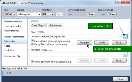
• In ‘Memories’ tab, select the HEX file and click ‘Program’ (see Figure 14).
The program will now run on the microcontroller. If you press and hold down one of the 8 switches on the STK500 board, the corresponding LED will be turned on.
A video demo of the program is available
This is the end of this introductory tutorial. More information about programming Atmel AVR microcontrollers for embedded applications is provided in ECTE333 Microcontroller Architecture and Applications subject, School of Electrical, Computer and Telecommunication Engineering, University of Wollongong, and also at http://www.uow.edu.au/~phung. Version history.
Source: Getting Started with C Programming for the ATMEL AVR Microcontrollers
- What software do I need to program AVR microcontrollers in C?
Atmel Studio (version 6 in the tutorial) and Microsoft Visual Studio 10 Service Pack 1 as a prerequisite. - How do I create a new C project for ATmega16 in Atmel Studio?
Select File | New Project, choose GCC C Executable Project, name it (led), enable Create directory for solution, then select ATmega16 in Device Selection. - How is the HEX file produced?
Use Build | Build Solution (F7) in Atmel Studio to compile the C code; led.hex will be generated in the debug or release subfolder. - Can I debug the program without the STK500 hardware?
Yes; use Debug | Start Debugging and Break and select Simulator to debug with Atmel Studio's simulator. - How do I view CPU registers and IO ports during debugging?
Select Debug | Windows and then Processor View or I/O View to examine registers and IO ports. - What hardware connections are required to program ATmega16 on the STK500?
Connect SPROG3 jumper to ISP6PIN, connect RS232 CTRL serial cable to the PC, and connect 12V DC power and turn it on; additionally connect SWITCHES to PORTA and LEDS to PORTB for the example. - How do I download the HEX file to the STK500?
In Atmel Studio add the STK500 tool via Tools | Add STK500, select the correct serial port, then use Device Programming, choose Tool=STK500, Device=ATmega16, Interface=ISP, select the HEX in Memories tab and click Program. - What happens when I run the programmed example on the STK500?
Pressing and holding one of the eight switches on the STK500 will turn on the corresponding LED.