Summary of GSM Based Fire Alarm System
This article details a GSM and microcontroller-based fire detection system that monitors temperature using an LM35 sensor and smoke levels with an MQ2 sensor. The system displays real-time data on a 16x2 LCD, triggers a buzzer alarm, disconnects electrical power upon detecting hazards, and sends SMS alerts to a predefined mobile number via a GSM modem. It is designed as a low-cost solution for fire monitoring and can be simulated using Protius software.
Parts used in the GSM Microcontroller Based Fire Detection System:
- Atmega 8 Microcontroller
- LM35 Temperature Sensor
- MQ2 Smoke Sensor
- 16x2 LCD
- BC548 Transistor
- 1K Ohm Resistors
- GSM Modem (SIM300 or SIM900)
- Buzzer
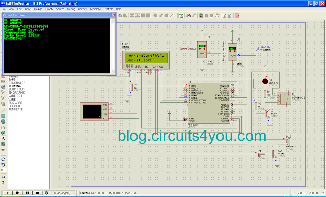
GSM, Microcontroller Based Fire detection and SMS Alert system, it uses LM35 Temperature Sensor and MQ2 for Smoke sensing and 16×2 LCD is used to display temperature and Smoke Level, Over limit set points are set inside the program you can modify it as per your requirements, It Sends SMS when set limits are crossed through GSM modem that is attached to Serial Rxd and Txd Pins, Set your mobile number inside the code in SendSMS subroutine. It generates Sound When Fire is detected for alerting.
Features:
1. Disconnects Electrical Supply as soon as Fire is detected
2. Sends Fire Alert SMS with Temperature and Smoke Level to Given number.
3. Makes Loud Sound using buzzer to alert about fire.
4. Uses Standard MQ2 Smoke Sensor and LM35 Temperature Sensor
5. Low Cost
This project is very useful for Monitoring of temperature, smoke level, It gives SMS Alert as soon as fire is detected.
In this project GSM Modem, MQ-2, LM35 are main parts. You can try this project using Protius simulation. Circuit diagram, Layout is provided with code. Download respective files.
1. Atmega 8 Microcontroller
2. LM35 Temprature Sensor
4. 16×2 LCD
5. BC548
6. 1K Ohm Resistors
7. GSM Modem (SIM300 or SIM900)
Download Requires Files
1. Try Simulation Click Here to Download Protius Simulation File
2. Download pdf Complete Circuit Diagram
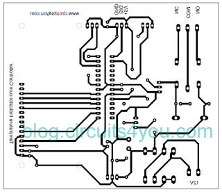
5. Assemble components using above files.
Step 3: Programming the controller
Download Hex File (You need to change phone number in code to get SMS)
AVR Studio C Code
//=================================================================
/* Fire Detection and SMS Alert System      */
/* 2nd Dec 2005                             */
/* Copyright 2005 Circuits4You.com          */
/* WWW - http://www.circuits4you.com        */
/* Email - [email protected]            */
//=================================================================
#include <avr/io.h>
#include <string.h>

#define E   PD7
#define RS   PB0

void display(char string[16], char LineNo);
void displaybyte(char D);
void dispinit(void);
void epulse(void);
void delay_ms(unsigned int de);

void USART_Transmit(char data );
void senddata(char string[16]);
void USART_Init();
void USART_Receive();
void sendSMS();

 char mystr[6];
 int Temperature,setpoint,Smoke,SmokeSet;
 unsigned char u8_data;
//=================================================================
//        Main Function
//=================================================================
int main(void)
{
 setpoint=60;  //Temprature Limit For detection of Fire
 SmokeSet=100; //Smoke Setpoint
 char Flag;

 DDRB = 0xF1;  //Set LCD Port Direction
 DDRD = 0xE0;
 PORTB = 0x06; //Pull up for switches

  delay_ms(500);  //Initiaize LCD
  dispinit();
  delay_ms(200);

 USART_Init();  //9600 Baud rate at internal ocillator Clock 1MHz

 display("Temperature:32 C",1);
 display("Smoke:55 PPM    ",2);
  while(1)
  {
    //Measure Temprature and Display
    ADMUX=0xE5;
    ADCSRA=0xC7;  //Internal Referance 2.56V
    while (!(ADCSRA & (1<<ADIF)));
    Temperature=ADCH;
    ADCSRA |= 1<<4;
    sprintf(mystr, "%03d", Temperature);
    display("Temperature:",1);
    displaybyte(mystr[1]);
    displaybyte(mystr[2]);
    displaybyte(0xDF);
    displaybyte('C');
    displaybyte(0x20);

    ADMUX=0xE4;   //Smoke Sensor
    ADCSRA=0xC7;  //Internal Referance 2.56V
    while (!(ADCSRA & (1<<ADIF)));
    Smoke=ADCH;   //Do some math here for calibration
    ADCSRA |= 1<<4;
    sprintf(mystr, "%03d", Smoke);
    display("Smoke:",2);
    displaybyte(mystr[0]);
    displaybyte(mystr[1]);
    displaybyte(mystr[2]);
    displaybyte('P');
    displaybyte('P');
    displaybyte('M');
    displaybyte(0x20);

  //Compare with Set Points and Send SMS
  if(Temperature>setpoint || Smoke>SmokeSet)
  {
   //Over Temprature SMS
     if(Flag==0)
     {
    sendSMS();
    Flag=1;
    PORTB &=~(1<<PB5);  //Turn of  Electrical Supply
    PORTB |=(1<<PB4);  //Turn on buzzer
     }
  }
  else
  {
   Flag=0;
   PORTB |=(1<<PB5);   //Keep on Electrical Supply
   PORTB &=~(1<<PB4);   //Turn off buzzer
  }
  }
}

//=================================================================
//        LCD Display Initialization Function
//=================================================================
void dispinit(void)
{
 int count;
 char init[]={0x43,0x03,0x03,0x02,0x28,0x01,0x0C,0x06,0x02,0x02};

 PORTB &= ~(1<<RS);           // RS=0
 for (count = 0; count <= 9; count++)
  {
 displaybyte(init[count]);
  }
 PORTB |= 1<<RS;    //RS=1
}


//=================================================================
//        Enable Pulse Function
//=================================================================
void epulse(void)
{
 PORTD |= 1<<E;
  delay_ms(1); //Adjust delay if required
 PORTD &= ~(1<<E);
 delay_ms(1); //Adjust delay if required
}


//=================================================================
//        Send Single Byte to LCD Display Function
//=================================================================
void displaybyte(char D)
{
//D4=PD6
//D5=PD5
//D6=PB7
//D7=PB6
 //data is in Temp Register
  char K1;
  K1=D;
  K1=K1 & 0xF0;
  K1=K1 >> 4;  //Send MSB

  PORTD &= 0x9F;  //Clear data pins
  PORTB &= 0x3F;

  if((K1 & 0x01)==0x01){PORTD |= (1<<PD6);}
  if((K1 & 0x02)==0x02){PORTD |= (1<<PD5);}
  if((K1 & 0x04)==0x04){PORTB |= (1<<PB7);}
  if((K1 & 0x08)==0x08){PORTB |= (1<<PB6);}

 epulse();

  K1=D;
  K1=K1 & 0x0F;  //Send LSB
  PORTD &= 0x9F;  //Clear data pins
  PORTB &= 0x3F;

  if((K1 & 0x01)==0x01){PORTD |= (1<<PD6);}
  if((K1 & 0x02)==0x02){PORTD |= (1<<PD5);}
  if((K1 & 0x04)==0x04){PORTB |= (1<<PB7);}
  if((K1 & 0x08)==0x08){PORTB |= (1<<PB6);}
 epulse();
}

//=================================================================
//        Display Line on LCD at desired location Function
//=================================================================
void display(char string[16], char LineNo)
{
 int len,count;

 PORTB &= ~(1<<RS);           // RS=0 Command Mode

 if(LineNo==1)
 {
  displaybyte(0x80);  //Move Coursor to Line 1
 }
 else
 {
  displaybyte(0xC0);  //Move Coursor to Line 2
 }
 PORTB |= (1<<RS);           // RS=1 Data Mode


  len = strlen(string);

   for (count=0;count<len;count++)
  {
    displaybyte(string[count]);
 }
}


//=================================================================
//        Delay Function
//=================================================================
void delay_ms(unsigned int de)
{
unsigned int rr,rr1;
   for (rr=0;rr<de;rr++)
   {

  for(rr1=0;rr1<30;rr1++)   //395
  {
   asm("nop");
  }

   }
}


void USART_Transmit(char data )
{
 UDR = data;
 /* Wait for empty transmit buffer */
 while ( !( UCSRA & (1<<UDRE)) )
 ;
 /* Put data into buffer, sends the data */

}


void senddata(char string[16])
{
  int len,count;
  len = strlen(string);

   for (count=0;count<len;count++)
  {
    USART_Transmit(string[count]);
 }
}

void USART_Init()
{
/* Set baud rate */
 UBRRH = 0x00;  //12, 9600 Baud At 1MHz
 UBRRL =12;
//Set double speed enabled
  UCSRA |= (1<<U2X);
/* Enable receiver and transmitter */
 UCSRB = (1<<RXEN)|(1<<TXEN);
/* Set frame format: 8data, 2stop bit */
 UCSRC = (1<<URSEL)|(1<<USBS)|(3<<UCSZ0);
//Set interrupt on RX
//  UCSRB |= (1<<RXCIE);
}

void USART_Receive()
{
/* Wait for data to be received */
while ( !(UCSRA & (1<<RXC)) )
;
/* Get and return received data from buffer */
u8_data=UDR;
}

void sendSMS()
{
     senddata("AT+CMGD=1");
     USART_Transmit(13);
     USART_Transmit(10);
     delay_ms(1000);

     senddata("AT+CMGF=1");
     USART_Transmit(13);
     USART_Transmit(10);
     delay_ms(1000);

     senddata("AT+CMGW=");
     USART_Transmit(34);
     senddata("+919812345678");  //Enter Your Mobile number
     USART_Transmit(34);
     USART_Transmit(13);
     USART_Transmit(10);
     delay_ms(1000);

     senddata("Alert: Fire Detected");
     USART_Transmit(13);
     USART_Transmit(10);
     delay_ms(1000);
     senddata("Temperature:");

     ADMUX=0xE5;
     ADCSRA=0xC7;  //Internal Referance 2.56V
     while (!(ADCSRA & (1<<ADIF)));
     Temperature=ADCH;
     ADCSRA |= 1<<4;

     sprintf(mystr, "%03d", Temperature);
     USART_Transmit(mystr[1]);
     USART_Transmit(mystr[2]);
     USART_Transmit('C');
     USART_Transmit(13);
     USART_Transmit(10);

     senddata("Smoke Level:");
     ADMUX=0xE4;   //Smoke Sensor
     ADCSRA=0xC7;  //Internal Referance 2.56V
     while (!(ADCSRA & (1<<ADIF)));
     Smoke=ADCH;   //Do some math here for calibration
     ADCSRA |= 1<<4;
     sprintf(mystr, "%03d", Smoke);
     USART_Transmit(mystr[0]);
     USART_Transmit(mystr[1]);
     USART_Transmit(mystr[2]);
     USART_Transmit('P');
     USART_Transmit('P');
     USART_Transmit('M');
     USART_Transmit(13);
     USART_Transmit(10);


     delay_ms(1000);
     USART_Transmit(26); //Cntrl+Z
     delay_ms(1000);
     delay_ms(1000);

     senddata("AT+CMSS=1");
     USART_Transmit(13);
     USART_Transmit(10);
     delay_ms(1000);
}


Step 4: Test the code and Hardware


1. Change temperature and Smoke level and observe the relay on/off, Buzzer operation.
2. LCD display Should show the message as shown in simulation results.
3. Follow us on Google+
4. You Did it Yourself
5. Refer Tutorials from this site for more understanding of code and Circuits
- How does the system alert users when fire is detected?
The system sends an SMS alert containing temperature and smoke levels, makes a loud sound using a buzzer, and disconnects the electrical supply. - What sensors are used to monitor environmental conditions?
The project uses an LM35 Temperature Sensor for temperature measurement and an MQ2 Smoke Sensor for smoke level detection. - Can the set points for fire detection be modified?
Yes, the over limit set points for temperature and smoke are defined inside the program code and can be modified as per requirements. - How is the SMS recipient number configured?
You must change the phone number inside the SendSMS subroutine within the code before compiling the hex file. - What happens to the electrical supply when a fire is detected?
The system automatically disconnects the electrical supply as soon as fire is detected by turning off the relay connected to PB5. - Is it possible to simulate this project before building the hardware?
Yes, you can try this project using Protius simulation software which includes the circuit diagram, layout, and code files. - What communication protocol is used between the microcontroller and the GSM modem?
The GSM modem is attached to the Serial Rxd and Txd pins of the microcontroller to facilitate SMS transmission. - What specific GSM modules are compatible with this design?
The project supports standard GSM modems such as the SIM300 or SIM900.