Summary of Handling the Digital Input Output in AVR Micro Controllers
This article introduces AVR microcontroller programming basics, focusing on Digital I/O using three registers per port: Data Direction Register (DDR), Data Output Register (PORT), and Data Input Register (PIN). It presents a C program for an Atmega8/Atmega32 to blink LEDs connected to Port B, utilizing the bitwise NOT operator and a delay loop.
Parts used in the Glow an LED using Avr Microcontroller project:
- Atmega8 microcontroller
- Atmega32 microcontroller
- LEDs
- Winzip or Winrar software
I have already discussed about a few chapters necessary to get into AVR programming. Now this is the first article that deals with programming. Let us start with the basics.
Digital input output (I/O) is the basic feature supported by AVR micro controller. To facilitate digital input output, three registers are associated with each port of the micro controller.
- Data Direction Register– This register determines which of the pins will act as an output port, and which of them as input.
- Data Output Register-This register holds the Data output to the port.
- Data Input Register– Reads data from the port
Now let us look into an example. For Port A the three registers are- DDRA, PORTA & PINA respectively. Similarly for port B, it will be- DDRB, PORTB & PINB.
Now before going to further discussion, there is one important thing I should mention. One port serves for more than one purpose. It is the designer’s responsibility to eliminate every possible error. If the program and system are not designed carefully, fallacy may appear.
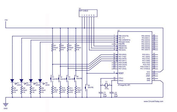
Circuit Diagrams using Atmega32 and Atmega8
Note: Click on the circuit diagram to get a large and clear view.
And find below the circuit using Atmega8
Glow an LED using Avr Microcontroller
Program 1: Basic Program Showing Digital Output functionality.
#include

#define F_CPU 1000000

#include

int main()
{ DDRB=0x0f;
PORTB=0x00;
while(1)
{ _delay_ms(1500);
PORTB =~PORTB;
}
return 0;
}
Description:
This program consists of two simple statements, including one delay loop. The ‘~’ symbol stands for bitwise not operation. Here CPU operating Frequency must be defined for proper implementation of the delay loop, and it has to be declared before the ‘delay.h’ line in the C code. Here I’ve used the #define F_CPU 1000000.
There is another option available to define the CPU Operating frequency. In Avr Studio, go to ‘Project Menu> Configuration Options> General’. Here you can choose your device model and its operating frequency.
As I’ve previously discussed, The Data direction register must be set up before doing any input/output operation.
Desired Output:
The LEDs connected to Port B blinks with 3 second time period.
Hex Files:
Note: All the HEX files given in this article are converted to RAR format (for safety and size reduction purpose). To get the HEX file as such – you may download each file and EXTRACT it to your computer using Winzip or Winrar.
Read more: Handling the Digital Input Output in AVR Micro Controllers
- What are the three registers associated with each port of the AVR microcontroller?
Data Direction Register, Data Output Register, and Data Input Register. - How do you define the CPU operating frequency in the C code?
You must declare it before the delay.h line using #define F_CPU. - Can you set the CPU frequency through Avr Studio?
Yes, by going to Project Menu, Configuration Options, and General. - Which register determines which pins act as input or output?
The Data Direction Register determines pin direction. - What is the desired output time period for the blinking LEDs?
The LEDs connected to Port B blink with a 3 second time period. - What does the ~ symbol represent in the provided C program?
The ~ symbol stands for the bitwise not operation. - Why must the Data direction register be set up before I/O operations?
It is necessary to configure the port correctly before performing any input/output operation. - In what format are the HEX files provided in the article?
All HEX files are converted to RAR format.