
Summary of Happy Christmas and Happy New Year wishes from Attiny13
The author salvaged a damaged Chinese camera pen's SPI flash memory and repurposed it into an 8K mono audio player using an Attiny13 microcontroller. Despite the chip's limited 1KB flash and 64 bytes RAM, the project successfully plays one-minute wav files by utilizing software SPI for memory access, a PWM pin for audio output, and UART for song updates. The design creatively reassigns pins to accommodate eight functional requirements within the device's five available GPIOs.
Parts used in the Attiny13 Audio Player:
- LE25U40CMD SPI flash memory
- TI Stellaris Launchpad
- Attiny13 microcontroller
- PWM pin (PB0)
- SPI pins (SO, SI, CS, SCK)
- UART communication interface
- Switch for song loading mode
- USB to UART converter or RS232 port
- MAX232 circuit
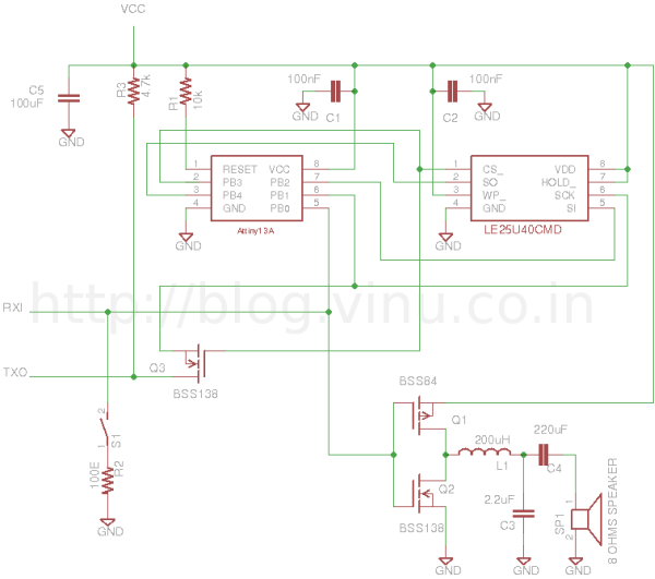
So all together 8 pins are required. But the controller have only 5 GPIOs. Out of this, PB0 is used as PWM for audio out. So I cannot use hardware SPI because PB0 is the MOSI pin for hardware SPI. So no other option, I have to use software SPI but it is not a problem. I used the other 4 pins for SPI. To update song in memory chip, I thought of using UART because it is the most popular way of communication between microcontroller and a PC, also most electronics hobbyist will have one usb to uart converter or an RS232 port and a MAX232 circuit. I used the same PWM pin as UART RX because it is having pin change interrupt feature. Also while flashing wav file, I don’t want to use the PWM function. Also it is the only free PIN which is not connected to the SPI port of the memory chip. Now I need a TX pin for sending ACK to the programmer and for proper handshaking while loading the song to memory chip. I used the SCK pin for this purpose. But SCK pin will toggle while communicating with the memory,
For more detail: Happy Christmas and Happy New Year wishes from Attiny13
- What type of flash memory was recovered from the camera pen?
The component is identified as a 4M-bit SPI flash memory similar to the LE25U40CMD. - How many GPIOs does the Attiny13 microcontroller have?
The Attiny13 has five GPIOs available for general use. - Why was software SPI chosen instead of hardware SPI?
Software SPI was required because the PB0 pin needed for hardware SPI MOSI was reserved for the audio PWM output. - How are songs updated to the flash memory?
Songs are updated using UART communication via a USB to UART converter or RS232 port with a MAX232 circuit. - Which pin is used for sending ACK signals during song loading?
The SCK pin is reused as a TX pin to send acknowledgments and handle handshaking while updating the file. - What audio format and quality does the player support?
The player supports 8K mono wav files that can play for approximately one minute.
