Summary of Home Appliance Control over Mobile Network
This article describes a system to control home appliances remotely via mobile phone. The user calls a specific number, and the system listens for DTMF tones generated by keypad presses. Keys 1-4 switch up to four loads like lights or fans. A DTMF decoder converts these tones into binary data sent to an ATmega8A microcontroller, which activates relays to control AC appliances.
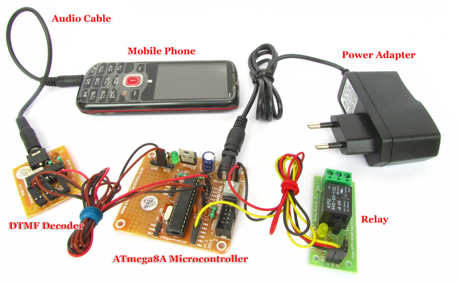
Parts used in the Home Appliance Control System:
- Mobile phone
- DTMF decoder module
- ATmega8A AVR microcontroller
- Output relays
- AC mains powered appliances (bulbs and fans)
- Audio cable
You can call up on your colleague‘s mobile number and ask him/her to turn on or off the lights or other appliance of your office. You may be any where in the world at that time, as mobile network allows to to talk to anyone present anywhere in this world. But your colleague is too much for this simple job! Your may replace him/her with this smart gadget and let it operate the appliances. But how it will do that? well, it will listen to the audio output from a mobile phone and try to recognise the DTMF tones present in the output sound. DTMF is a way to encode numerical data into an audible sound which is then sent over an audio channel. Keypress on the other mobile will generate DTMF codes.
Keys like 1,2,3 and 4 are used to switch on/off up to four loads like light, fan, water pump in a building.
The user(who is away from home) using his/her mobile phone calls another mobile (which is present at the home and is attached to the this system) and then press keys on his/her mobile phone to controls the load in the home. The mobile attached to the system receives tones from the user’s mobile and sends them to the DTMF decoder module over an audio cable. The DTMF decoder module converts this tone to a 4 bit binary number which is then sent to a ATmega8A AVR microcontroller which controls output relays using four of its port pins. These relays can be used to switch AC mains powered appliances like bulbs and fans.
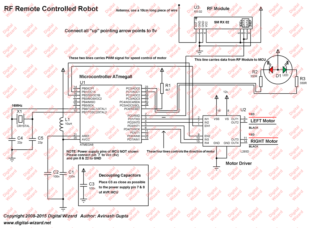
Circuit Design
For the design of radio controlled robot we have chosen AVR ATmega8 microcontroller. Which is a very popular, low cost and easily available microcontroller. It receives data from RF module on its serial data receive pin, that is RXD (PIN 2). Then it processes the data and generates control signal for the two motors (left and right). It also generates the PWM signal on its OC1A and OC1B pins (pin 15 & 16), this PWM signal is used to control the speed of the two motors. OC1A controls the speed of left motor, while OC1B controls the speed of right motor. Four general purpose input output lines of PORTD(PD1, PD2,PD3 and PD4) are used to control the direction of motors. The output from the microcontroller’s pins are not strong enough to provide enough voltage and current to drive motors directly. So we need to use motor driver IC like L293D.
for more detail:Home Appliance Control over Mobile Network
- How does the system recognize commands from a mobile phone?
The system listens to audio output from a mobile phone and recognizes DTMF tones present in the sound. - What function do keys 1, 2, 3, and 4 serve?
These keys are used to switch on or off up to four loads such as lights, fans, or water pumps. - How is the DTMF tone converted into a signal for the microcontroller?
The DTMF decoder module converts the received tone into a 4 bit binary number. - Which microcontroller controls the output relays in this project?
An ATmega8A AVR microcontroller controls the output relays using four of its port pins. - Can this system be operated from anywhere in the world?
Yes, because the mobile network allows communication with anyone present anywhere in the world. - What type of appliances can be controlled by this gadget?
The relays can switch AC mains powered appliances like bulbs and fans.