Summary of Home Automation – RC Lighting
This project demonstrates how to automate an AC appliance, such as a ceiling fan or light, using the LinkIt ONE board and an infrared (IR) remote. The system detects IR signals from any standard remote and triggers a relay to switch high-voltage devices on or off. Key steps include safely cutting power, modifying the appliance's wiring, enclosing the electronics in a box, and uploading custom code that filters out ambient IR interference.
Parts used in the LinkIt ONE Home Automation Project:
- LinkIt ONE Dev Board
- 5v Relay
- Box
- IR Reciever
- Wires
- Electrical Tape
- Screw Driver
- Wire Cutters
- Knife/Razor
- Flashlight
Is there an appliance in your house that you wished could be turned on easier? That hard to reach light that you need every day or a fan? With the LinkIt ONE we can do just that! Specifically we can control an AC appliance with a remote control! There are many different appliances around the house that this would work for. There are also many different ways of automating your home. I chose to use an Infra-red remote control.
Do I have to have a specific remote you may be wondering? No! Any and every infra-red remote will work. In the code I made the IR receiver look for any infra-red signal. Once, received it turns the light on.
How does it work? The LinkIt ONE is programmed to listen for infra-red signals. If it gets one, it will then activate a relay which will then turn on the light. Because we are dealing with AC voltage we cannot simply use a digital pin directly. Thats where the relay comes in. A relay is basically a switch capable of switching on and off high voltages with small voltage inputs.
WARNING: I am not responsible for any harm that you experience because of this instructable. High voltage is dangerous! Straight from Wikipedia, “Voltages greater than 50 V applied across dry unbroken human skin can cause heart fibrillation if they produce electric currents in body tissues that happen to pass through the chest area.[citation needed] The voltage at which there is the danger of electrocution depends on the electrical conductivity of dry human skin. Living human tissue can be protected from damage by the insulating characteristics of dry skin up to around 50 volts. If the same skin becomes wet, if there are wounds, or if the voltage is applied to electrodes that penetrate the skin, then even voltage sources below 40 V can be lethal.” U.S. homes have voltages of 220!
Also, I want to upfront apologize for any blurry pictures! Sorry about that!
Now that I have scarred you, lets get started!
Materials
Step 1: Picking Your Appliance & More Safety
In order for the following steps to be helpful I suggest you try this on a light first. I will demonstrate the method using the light part of a ceiling fan. Basically anything that has a switch in it to turn it on/off will work. Even if it does not have a switch you can do this by cutting one of the wires and putting our project in between.
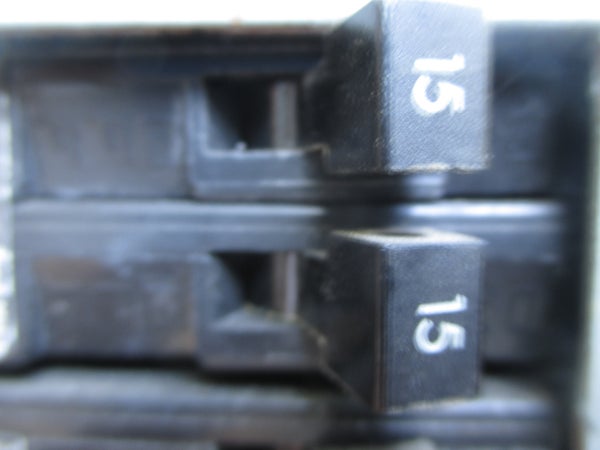
The best way to work safely is to cut the power to your appliance. If it is something you plug in the wall that is easy obviously. If it attached semi-permanently like a ceiling fan then it is a little harder.
The best thing to do in that case is flip the breaker. If you are not sure which one it is then you will have to do some guess work. First power down all computers that rely on external power. Then turn on the appliance you are working on. Have someone tell you when it turns off as you try different ones. Hopefully yours are labeled and you won’t have to do this. Another precaution is to where some sort of insulation such as gloves.
Step 2: Tools

Obviously everyone’s tools will be different but here are some things you will need regardless of what type of appliance you are working on.
- Electrical Tape or other insulator
- Wire Cutters
- Screw Driver
- Knife/Razor
- Flashlight
- Wire
If you are working in a windowless room or an otherwise dark area a flashlight is a must. The electrical tape is for insulating any wires we cut. You could also use wire nuts, duct tape, or even heat shrink if it is sufficiently large. Wire is useful if you have to extend a wire you cut. Make sure you get a gauge of wire that will withstand AC current.
Step 3: LinkIt ONE Enclosure
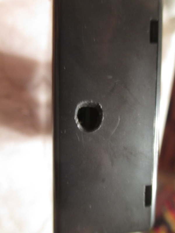
You will want some sort of box to cover up the electronics part that you are adding so it does not look too messy. I used a plastic box. On one side I made a rectanglish hole for the IR receiver and on the other side I made a small hole for the relay wires. Make sure there is room for the battery that came with your board to fit.
The wire I used for the IR Receiver is from an old servo that I thought was broken when I cut it, but that’s a different story. It worked perfectly for its new purpose. I had to bend the jumper wires so I could fit the lid on but that was OK with me.
Step 4: Code

The code is very simple. All it does is wait for a signal and then turn the light on/off depending on what its current state is.
However, initially getting the remote to work was a pain. The traditional IRemote library will not work because it cannot compile on the LinkIt ONE. So I searched and found a library specific to the board. Download it and install it in your IDE. Now you can use infra-red receivers. Apparently, it only works on digital pin 2 and that is what I have wired the receiver too.
I also had a problem with the library after installing it. In the main loop, once I pushed the button once it would continue to turn the light on and off, on and off. I had no idea why because the if function checked for a signal before it was executed and then did it only once. I finally found out that I needed to so called flush out the old received value. Once I added that it worked perfectly at first! I also added a delay of 5 seconds after you press the button because it keeps extra button presses from effecting the state of the light. Also, it is probably not that good for the light-bulbs to be turned on and off very quickly.
The reason I say at first it worked is because after being installed for a while it started turning on/off randomly. I had it installed in my bedroom and in the middle of the night it turned on, off, on, off. Ahhhhhhhhh! What is it doing!! I then realized that since I had made the code accept any infrared value that the light bulbs on the fan were effecting it because they emit infra-red light! So i added a little duck tape filter that focused the receiver so it would only be able to get signals from a certain direction. It worked!
So upload the code provided and make sure first that the library is installed.
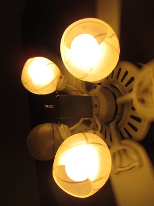
Step 5: Disecting the Fan – Accessing the Electronics

Above you can see our unfortunate victim of experimentation.The chain coming out will be replaced with our contraption. On my fan, I only had to remove two screws. Lay them aside along with the cover in a safe place. Then remove the fastener by the chain that holds the switch in place.
Step 6: Disecting the Fan – Removing the Switch
Now, pull out the switch and trace each wire. If there is one that leads to a wire nut then unscrew it and remove that side. You will have probably have to cut a wire unless both ends terminate at a wire nut. Make sure to leave all the other wires in the wire nut at the same place.
My apologies for the bad pictures. I had to take them in the dark while holding a flash light because the room did not have power.
Don’t cut the wires right at the end or you will not be able to put the other piece back if something goes wrong. Use the pictures for reference.
Step 7: Preparing for Installation
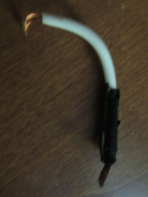
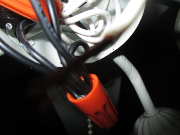
If there were wire nuts than you will need to add an extra wire since you took the switch out. Cut a piece of wire and strip half an inch from both sides. Now unscrew each wire nut and put the new wire in. If there was no wire nut and you had to cut the wire then check the length. If it is too short than cut another wire following the same process and twist it together with the old end. Wrap the connection with electrical tape for insulation.
Step 8: Installing the Relay
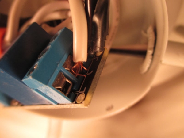
The relay we are using has two sides with three ports on each side. We want the side with the curvie lines. See the pictures above. Looking at the relay upside up we will be using the two right slots. Push the two wires in from the last step, order does not matter, and screw them down.
On the other side we will install the wires for the input. First wire them through the hole that used to house the switch. Screw down the 3 wires to the other side. From left to right it goes 5v, Signal(pin 13), and ground. Once you have them through the hole, put them through the circle hole in the box and then plug them into the board. Make sure you plug Vcc into 5v and not 3.3v. It is a 5v relay. It only accepts 3.3v logic.
In the pictures follow the jumper wires, not the servo wire.
Source: Home Automation – RC Lighting
- Does this project require a specific brand of remote control?
No, any standard infra-red remote will work because the code is programmed to accept any infra-red signal. - How does the LinkIt ONE activate the appliance?
The board listens for infra-red signals and activates a relay, which acts as a switch to handle the high voltage required by the appliance. - Can I use a digital pin directly to control the AC voltage?
No, you cannot use a digital pin directly for AC voltage; a relay is required to bridge the small input voltage with the high output voltage. - What caused the light to turn on and off randomly during testing?
Ambient infra-red light emitted by the fan bulbs was being picked up by the receiver, so a duct tape filter was added to block stray signals. - Why was a 5-second delay added to the code?
The delay prevents extra button presses from affecting the light state immediately and protects the bulb from rapid on-off cycling. - Which digital pin must be used for the IR receiver?
The specific library for the LinkIt ONE only works on digital pin 2. - What safety precaution is recommended before working on a permanently installed appliance?
You should flip the circuit breaker to cut power, as simply unplugging the device may not work for hardwired items like ceiling fans. - How should the relay wires be connected to the LinkIt ONE board?
The Vcc wire connects to 5v, the Signal wire connects to pin 13, and the ground wire connects to ground.