Summary of How to use LabVIEW to program an FPGA
LabVIEW is a graphical programming environment by National Instruments for control, measurement, and FPGA development. The article explains downloading and activating LabVIEW, using its front panel and block diagram, basic VI creation and tools, running examples, and programming FPGAs via the LabVIEW FPGA module. It also covers hardware connections for cRIO systems, required software components, creating an FPGA project, wiring FPGA I/O modules in a VI, and compiling to the LabVIEW FPGA Compile Cloud Service.
Parts used in the LabVIEW FPGA Project:
- Host PC (Windows-based)
- LabVIEW software
- LabVIEW Real-Time Module
- LabVIEW FPGA Module
- NI-RIO Driver
- cRIO chassis (example cRIO-9076 / cRIO-9078)
- Input module (Mod1 with DI0)
- Output module (Mod2 with DO0 and DO1)
- 24 VDC power source
- Toggle switch
- Network cable (Ethernet)
- LabVIEW FPGA Compile Cloud Service (NI credentials for access)
Table of contents
1 What is labview?
2 Video about using LabVIEW to program an FPGA
3 Labview Tutorial
4 How to use LabVIEW to program an FPGA
5 Hardware Connections
6 To run the LabVIEW Software
What is labview?
LabVIEW, a graphical programming environment created by National Instruments, is a well-known tool in research and industrial engineering (especially with control, measurement, and test applications) for the past 20 or so years. Unfortunately, it is neither open-sourced or free, like many other industrial tools.
Because it enables complicated programming tasks to be completed in a fraction of the time compared to using other programming languages, LabVIEW is powerful. Additionally, whether you’re programming for your PC, an Arduino, or a piece of National Instruments hardware, LabVIEW programming is fundamentally the same for all targets. Even Field Programmable Gate Arrays (FPGAs), reconfigurable hardware that can achieve unprecedented speed and reliability, may be programmed using the same environment and programming ideas.
Furthermore, conventional wisdom dictates that you must use proprietary languages like VHDL and Verilog to design FPGAs. In this instance, we’ll use LabVIEW, a universally compatible programming language. Although this course aims to serve as many people as possible, a foundational knowledge of LabVIEW is required. FPGA includes many family series like Zynq-7000 SoC, FPGA Spartan-7, Artix-7 FPGA, Virtex-7 FPGAs, Kintex-7 FPGAs, and so on which are all used LabVIEW to more efficiently and effectively design FPGA-based systems through a highly integrated development environment, IP libraries, a high-fidelity simulator, and debugging features.
Video about using LabVIEW to program an FPGA
Labview Tutorial
Step One: Download Labview
Install LabVIEW. Launch the program after your download is finished. This process installs Package Manager or, if necessary, upgrades it. After installing Package Manager, follow the on-screen instructions to finish installing LabVIEW. The Activation Wizard launches automatically following installation completion. The instructions will help you activate your program. You might require further activation details if you’re activating through a license agreement or on a computer that isn’t online.
Labview Certification:
You or your purchasing representative will get an email to claim access to NI software after purchasing LabVIEW or other software modules. To finish your claim, log into your ni.com account and click the email’s ACCEPT ACCESS button.You will get a screen that validates your access and contains a link to download the software after you have requested access to it. Use this link to get your program if you haven’t already.
If you don’t have or didn’t receive this email, take the following actions: Head over to the LabVIEW Download Page.
After choosing the desired LabVIEW version, click Download. You will be requested to log in if you are not already. Refer to Download Older Versions of NI Software for earlier versions of LabVIEW.
Step Two: Labview Environment
Because they frequently mimic actual instruments like oscilloscopes and multimeters in both appearance and functionality, LabVIEW programs are sometimes known as virtual instruments, or VIs. A complete range of tools for gathering, analyzing, displaying, and storing data, as well as tools to assist you in troubleshooting the code you develop, are included with LabVIEW.
The block diagram and the front panel are the two windows you see when you create a new VI. The LabVIEW program’s graphical source code is contained in the block diagram, and the front panel serves as the VI’s user interface.

The front panel window serves as the VI’s user interface. By adding controls and indicators to a VI’s front panel, you can design the user interface of the VI. Inputs are defined by controls, and outputs are shown by indicators. Among other block diagram objects, wires, terminals, subVIs, functions, constants, and structures are block diagram objects that convey data.
Step Three: Labview Programming
A VI can be created, modified, and debugged using LabVIEW tools. A tool is a specific operating mode of the mouse cursor, hence the icon of the currently selected tool corresponds to the cursor’s operating mode.
Based on the mouse’s current position, LabVIEW decides which tool to employ. By choosing View»Tools Palette from the menu bar, you can manually select the tool you require from the Tools palette. You can now select the tool of your choice, which stays selected until you select a different tool from the Tools palette.
Step Four: Regular Tools
- VI Toolbar: Your VI has a toolbar that is connected to each window. To execute and edit the VI, use the front panel window toolbar buttons.
- Detection Tools: Debugging tools are included with LabVIEW software to assist you in finding problematic portions of your code and making the necessary corrections. There are two main categories of software bugs that you could run into: those that stop the program from working and those that produce undesirable outcomes or improper behavior.
- Help Context Window: When you move the cursor over any LabVIEW object, the Context Help box pops up with some basic information about the object. Select Help » Show Context Help, press Ctrl+H, or click the Show Context Help Window button on the toolbar to toggle the Context Help window’s appearance.
- NI Example Finder: To explore or search examples installed on your computer, use the NI Example Finder. LabVIEW performs searches among the thousands of sample VIs available for use and incorporation into custom VIs. You can edit an example to suit your needs or copy and paste code from one or more examples into a VI you design.
Step Five: Running Examples
- From the toolbar, select a new blank VI. Choose File » New VI.
- Drag two multiply functions from the Programming >> Numeric subpalette onto the block diagram to add them to the diagram.
- The input and output terminals will become visible when you move your mouse over the multiply function on the left.
- Hovering your mouse over the output terminal of the left multiply function will allow you to connect it to the x input of the right multiply function. Click and hold as you move the wire to the desired input once it has changed into the wiring spool.
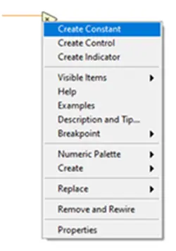
- Make a constant for the triangular multiplier.5 by selecting Create»Constant from the context menu when you right-click on the y input terminal of the multiply function on the right. By double-clicking a constant to highlight the text and enter the new value, you can modify its value. Enter after you enter.5.
- Create an indicator that sends the value of the block diagram logic to the front panel by selecting Create»Indicator from the context menu of the right-clicked output of the right multiply function.
- By hitting Ctrl+E or choosing Window»Show Front Panel, view the front panel that was produced as a result of your work on the block diagram.
- Choose a While Loop from the Programming >> Structures subpalette to place on the block diagram.
- The Conditional Terminal is located in the bottom right corner of the while loop. Right-clicking the terminal and choosing Create Control will add a Stop button. On the front panel, the newly generated button is automatically shown.
- Change the values on the front panel of the newly constructed VI by clicking the Run button.
- To stop the VI, click the Stop button. By choosing File»Save from the menu bar and then hitting the Close button in the top right corner of the front panel window, you can save and exit the VI.
Step Six:
New project beginning: You are prepared to start developing your application once you have installed your software and become comfortable with the LabVIEW development environment.
How to use LabVIEW to program an FPGA
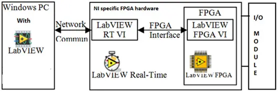
Through the LabVIEW FPGA add-on module, you may program an FPGA using LabVIEW, and you can design FPGA-based systems more successfully and quickly with a highly integrateddevelopment environment that includes IP libraries, a high-fidelity simulator, and debugging tools. It aids in creating FPGA VIs that mix direct I/O access with user-defined LabVIEW logic toconstruct bespoke hardware for uses including quick control prototyping, hardware-in-the-loop simulation, and digital protocol communication. It has numerous integrated signal processing operations. Additionally, you can incorporate third-party IP and already-written HDL (hardware description language) code. Utilize this module to program a variety of hardware made by NI, such as CompactRIO Systems (cRIO), FlexRIO, PXI Multifunction Reconfigurable I/O Module, Industrial Controllers, etc. Below shows a general block diagram to program NI FPGA hardware using LabVIEW.
Hardware Connections
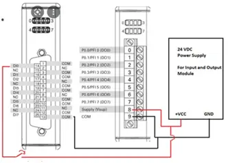
Hardware connections are created where the input and output module has been connected into the cRIO chassis slot, as seen in the image below. The input module’s DI0 channel is linked in series with a toggle switch and a 24 VDC power source. The output module is powered by 24VDC, and its DO0 and DO1 channels can be used to monitor output. Utilize a network cable to connect the host PC to the cRIO chassis (the blue cord in the illustration).
On the windows-based host PC, we must install LabVIEW, LabVIEW Real-Time Module, LabVIEW FPGA Module, and NI-RIO Driver before we can implement the LabVIEW program.
To run the LabVIEW Software
Step One:
Create a LabVIEW FPGA project by launching the LabVIEW application; this will cause the project window to open and detect any connected hardware.
Step Two:
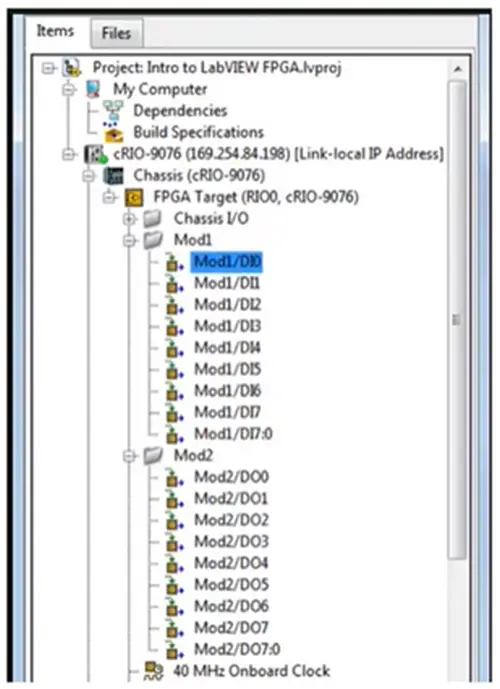
My Computer, which is to construct an application on the host computer, and c-RIO-9078 (169.254…), which is to create an application on the target RT machine (cRIO-9076), are the two categories included in this project window. Now right-click on cRIO-9076->Chassis (cRIO-9076)->FPGA Target (RIDO, cRIO-9076), move there, and create a new VI to open the window as shown in the image below. This VI’s code will execute immediately on the target machine.
Step Three:
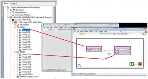
To access its input and output channels, such as Mod1 and Mod2, the FPGA target includes an integrated sub-VI. Drag sub-VI Mod1/DI0, Mod2/DO0, and Mod2/DO0 on the block diagram and connect as indicated in below picture. Navigate to cRIO-9076->Chassis (cRIO-9076)-Mod1 and cRIO-9076->Chassis (cRIO-9076)-Mod2. Put the code within a while loop and tie the control to the Boolean constant FALSE (F) to make it run continually. The code demonstrates that DO0 will be low and DO1 will be high when we input DI0 at high logic (24V). It will be inverted with a low input.
Step Four:
After finishing the code, press the “RUN” button to launch a new window where the target computer will compile the code. Click “OK” after selecting “Connect to LabVIEW FPGA Compile Cloud Service” and entering your NI credentials.
- How do I install LabVIEW?
Download LabVIEW, run the installer which installs Package Manager, follow on-screen instructions, and complete activation via the Activation Wizard or ni.com licensing flow. - Can I program an FPGA with LabVIEW?
Yes, using the LabVIEW FPGA add-on module you can design FPGA VIs and program NI FPGA hardware. - What software must be installed on the host PC?
Install LabVIEW, LabVIEW Real-Time Module, LabVIEW FPGA Module, and NI-RIO Driver on the Windows host PC. - How are hardware connections made for cRIO I/O?
Connect the input module DI0 in series with a toggle switch and 24 VDC, power output module with 24 VDC, and link host PC to cRIO chassis via network cable. - How do I create a LabVIEW FPGA project?
Launch LabVIEW to open the project window, detect connected hardware, and add My Computer and the cRIO target; then create a new VI under the FPGA Target. - How do I access FPGA I/O channels in a VI?
Drag the integrated sub-VIs for the target I/O (for example Mod1/DI0, Mod2/DO0, Mod2/DO1) onto the block diagram and wire them inside a while loop. - What example logic is shown for DI0 and DO0/DO1?
The example ties the loop to run continuously and demonstrates that when DI0 is high (24V), DO0 will be low and DO1 high, with inversion when input is low. - How do I compile the FPGA code?
Press Run to compile on the target; choose Connect to LabVIEW FPGA Compile Cloud Service, enter NI credentials, and proceed with compilation.