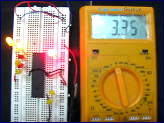
ATmega16 has 32 I/O pins to communicate with external devices. Before interfacing with external devices, these pins must be cofigured as input or output pin. This article demonstrates the basic I/O operation of ATmega 16 using LEDs.
All the four ports can be configured to read an input from some external device or to give output to any external device as per the application. For e.g., a switch is connected to a particular pin, that pin should be configured as input to read the values from the switch (external Device in this case) and if you are connecting a LED to any pin of the port then that particular pin should be configured as output to transmit the signal to the LED (external device in this case). A single port can be configured such that some of the pins of the same port are input and some are output.
Configuring IO Ports:
Every port (PORTx, x = A or B or C or D) of AVR microcontrollers have three registers associated with it:
1. DDRx: Data direction Register, to set the direction of each pin of PORTx and configuring it to be as input or output.
2. PORTx: The values which are to be supplied at the output of the port are written in this register. These values acts as input to the device connected at output port of the microcontroller (through PORTx output configured pins).
3. PINx: This register stores the input value from the external connected hardware, when the port is configured as input port. The input data is read from PINx register.
So the first step in configuring or initializing any of the IO port is to set its direction in data direction register (DDRx) to define the behavior of individual pins as input or output. A high (1) in any bit of the DDRx register means the corresponding pin is set as output and vice versa.
Example: Considering switch-LED scenario, suppose a switch is connected to Pin5 (PORTD.4) of PORTD and LED is connected to Pin8 (PORTD.7) of PORTD. Now we need to initialize the pins accordingly. The other pins of PORTD are not used in this case so they can be ignored as of now.
STEP-1: In order to configure PORTD.4 as input the value of Pin-5 (DDRD.5) in DDRD register is made 0.
|
DDRD.7
|
DDRD.6
|
DDRD.5
|
DDRD.4
|
DDRD.3
|
DDRD.2
|
DDRD.1
|
DDRD.0
|
|
–
|
–
|
0
|
–
|
–
|
–
|
–
|
–
|
Step-2: To initialize PORTD.7 as output the value of Pin-8 (DDRD.7) in DDRD register is made 1.
|
DDRD.7
|
DDRD.6
|
DDRD.5
|
DDRD.4
|
DDRD.3
|
DDRD.2
|
DDRD.1
|
DDRD.0
|
|
1
|
–
|
0
|
–
|
–
|
–
|
–
|
–
|
Step-3: Rest of the pins can have any value as they are not being used in this case. The default values of DDRx register is 0 for each pin i.e., all the ports of AVR microcontrollers are initialized as input.
|
DDRD.7
|
DDRD.6
|
DDRD.5
|
DDRD.4
|
DDRD.3
|
DDRD.2
|
DDRD.1
|
DDRD.0
|
|
1
|
0
|
0
|
0
|
0
|
0
|
0
|
0
|
So the value of DDRD will be initialized as 0x80.
For more detail: How to interface LED with AVR Microcontroller (ATmega16)