Knowingly or unknowingly the RFID technology is used by us in our day to day life. The most familiar example is seen in MNCs, schools and offices for daily attendance or automatic door opening system. The RFID contains two parts, namely, tag and receiver modem. When an RFID tag comes in the range of receiver, the tag gets activated and transmits its unique identification code to the receiver module.
The output of the RFID receiver is the unique ID in either serial (RS232) or wiegand format. Most of the receivers are equipped with additional hardware to send the extracted code in the above format, which can then be used by digital signal processors. This article shows the interfacing of ATmega16 with RFID.
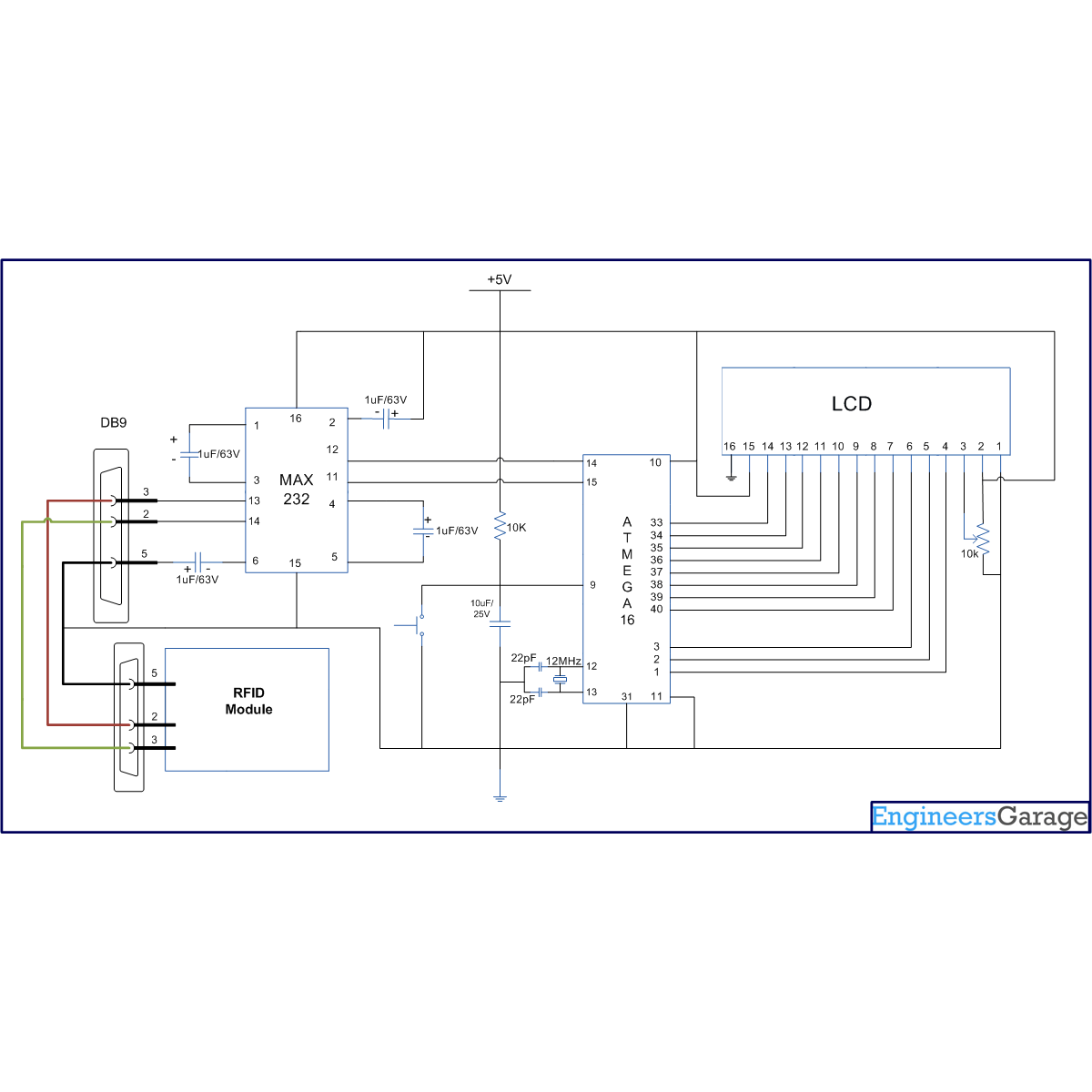
The RFID module used here gives a 12 byte unique ID of a particular tag in serial RS232 logic level format. Hence a level converter MAX232 is used in between RFID receiver module and microcontroller. The connections of RFID module and ATmega16 are shown in thecircuit diagram. The ground pin of MAX232 and serial output of RFID module is made common. A cross cable connection is set up between the RFID module and the MAX232 by connecting transmitter pin of one to the receiver pin of the other and vice versa as shown in the circuit diagram.
Note: In case the output of the RFID module is in TTL format, there is no need of MAX232. In such a case the output of the RFID module can be directly given to the microcontroller.
Pin 2 of max 232 | Pin 3 of RFID modem |
Pin 3 of max 232 | Pin 2 of RFID modem |
Pin 5 ground pin of max 232 | Pin 5 ground of RFID modem |
Code description
In order to understand the code for RFID (given below) which is interfaced with ATmega16, one must have a basic knowledge of serial communication and LCD. The serial data from RFID module can be taken by microcontroller either by polling or by using serial interrupt concepts. (To understand the difference between them, refer to tutorial on Interrupts) This article explores the interfacing of RFID module with AVR microcontroller (ATmega16) using the polling technique. The code described here keeps monitoring the serial input till it receives all the twelve bytes from the RFID module.
Receiving 12 byte serial interrupt data by polling method:
Steps to receive twelve byte serial data
i. Initialize USART in read mode.
ii. Get a 12 byte string (RFID card no.)
For more detail: How to interface RFID with AVR microcontroller (ATmega16)


