Summary of Interfacing an ATmega32 Microcontroller with a 4×4 Keypad
This tutorial details interfacing a 4x4 keypad with an ATmega32 microcontroller to display pressed keys on a 16x2 LCD. It explains the multiplexing technique used to reduce pin usage for the keypad and provides specific wiring connections between the microcontroller, LCD, and keypad. The article includes a complete C code implementation using Atmel Studio to scan the matrix, identify inputs, and output characters to the screen.
Parts used in the Interfacing an ATmega32 Microcontroller Project:
- ATmega32 microcontroller
- 5V power supply
- AVR-ISP programmer
- JHD_162A LCD (16x2)
- 100μF capacitor
- 100nF capacitor
- Eight 10KΩ resistors
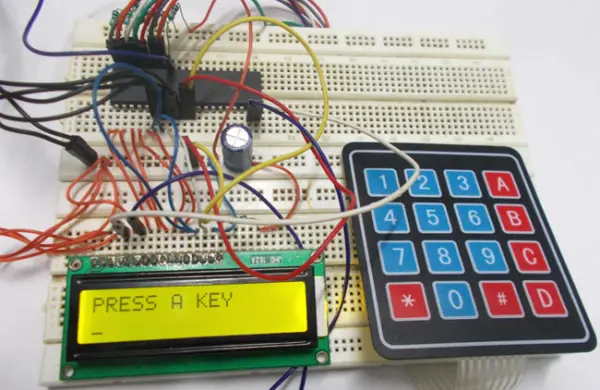
Interfacing an ATmega32 microcontroller, this tutorial demonstrates the connection of a 4×4 (16-key) keypad with the ATmega32A microcontroller. Keyboards are recognized as essential input devices in electronic projects, providing a straightforward means to convey commands or directives to an electronic system.
Necessary Components
Hardware Components: ATmega32 microcontroller, 5V power supply, AVR-ISP programmer, JHD_162A LCD (16×2), a 100μF capacitor, a 100nF capacitor, and eight 10KΩ resistors.
Software Requirements: Atmel Studio 6.1 or Atmel Studio 6.2, along with ProgISP or Flash Magic
Circuit Schematic and Operational Description
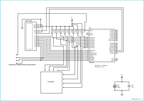
Within the circuit, the ATmega32’s PORTB is connected to the LCD’s data port. It’s important to note that if you intend to use PORTC for regular communication, you should disable JTAG communication by adjusting the fuse bytes. In the case of a 16×2 LCD, it features a total of 16 pins, which includes backlit variants. If there’s no backlight, it comprises 14 pins. You have the option to connect or omit the backlight pins. Among the 14 pins, there are 8 data pins (labeled 7-14 or D0-D7), 2 power supply pins (1 and 2, or VSS and VDD, which correspond to ground and +5V), a third pin for contrast control (VEE, controlling character thickness), and 3 control pins (RS, RW, and E).
In the circuit, it’s noticeable that I’ve utilized only two control pins, offering increased flexibility. The contrast bit and READ/WRITE pins are infrequently employed, so they can be connected to ground. This effectively sets the LCD to its maximum contrast and read mode. To transmit characters and data as needed, we only need to manage the ENABLE and RS pins.
The following outlines the connections made for the LCD:
PIN1 or VSS to ground
PIN2 or VDD or VCC to +5v power
PIN3 or VEE to ground (gives maximum contrast best for a beginner)
PIN4 or RS (Register Selection) to PD6 of uC
PIN5 or RW (Read/Write) to ground (puts LCD in read mode eases the communication for user)
PIN6 or E (Enable) to PD5 of uC
PIN7 or D0 to PB0 of uC
PIN8 or D1 to PB1 of uC
PIN9 or D2 to PB2 of uC
PIN10 or D3 to PB3 of uC
PIN11 or D4 to PB4 of uC
PIN12 or D5 to PB5 of uC
PIN13 or D6 to PB6 of uC
PIN14 or D7to PB7 of uC
In the circuit, you can observe that we’ve implemented 8-bit communication (D0-D7). However, it’s not mandatory; you can opt for 4-bit communication (D4-D7), although this makes the programming slightly more intricate. Therefore, by a simple examination of the table above, we’re linking a total of 10 pins from the LCD to the controller, with 8 pins designated for data and 2 pins for control.
Now, let’s discuss the keypad. A keypad essentially consists of multiplexed keys, where buttons are arranged in a multiplexed configuration to minimize the number of pins required for the control system.
Imagine we have a 4×4 keypad, which comprises 16 buttons. In typical situations, you’d require 16 controller pins to connect these 16 buttons, but this isn’t efficient from a control system perspective. To optimize pin usage, these buttons can be interconnected in a multiplexed configuration.
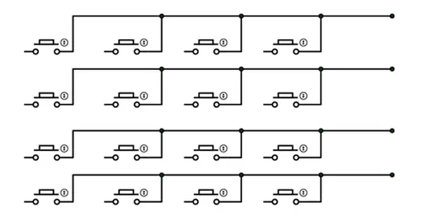
For instance, let’s take 16 buttons that we want to link to a controller to create a keypad. These buttons are organized as depicted in the illustration:
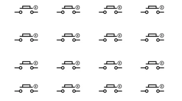
These buttons are linked via shared columns, as illustrated in the diagram:
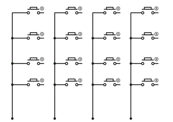
As depicted in the diagram, the unmarked terminals of every set of four buttons are combined to create a column. For all 16 keys, this results in four columns.
If we disregard the column connections described earlier and instead join the common marked terminals of every set of four buttons to establish a row:
As illustrated in the diagram, when dealing with 16 keys, we will have four rows, as shown.
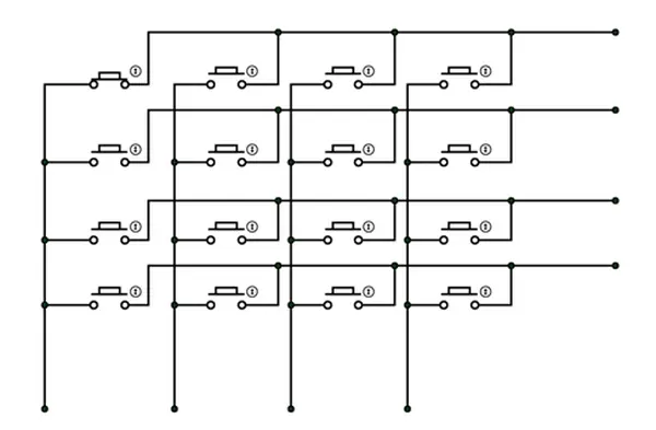
When we observe them in conjunction, we end up with a circuit resembling the one depicted below:
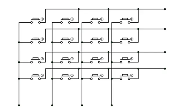
In this arrangement, we’ve interconnected the 16 keys in a multiplexed manner to minimize the number of controller pins required. In contrast to the initial scenario where we would have needed 16 pins on the controller to connect 16 keys, multiplexing has reduced the requirement to just 8 controller pins.
Typically, this is what you find within a keypad:
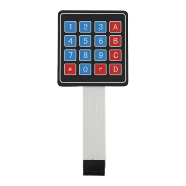
As depicted in the previous illustration, the keypad contains a total of 16 keys, with each key corresponding to a button in the multiplexed button configuration. Additionally, there are 8 pin connections, as denoted in the symbolized diagram above, representing the multiplexed connections.
Now for working:
In this keypad, there are both four columns and four rows. To determine which button is pressed, we will employ a cross-reference method. Initially, we have the option to link either all columns or all rows to the Vcc. If we connect the rows to a common Vcc, the columns will be utilized as inputs to the controller.
If we press button one, as depicted in the illustration:
Following this action, a current passes through the circuit, as indicated in the subsequent illustration:
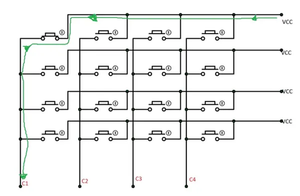
As a result, C1 is in a high state when a button is pressed. At this point, we will transition the power and input ports, meaning we will energize the columns and use the rows as inputs.
As a result, a power flow will occur, as depicted in the subsequent illustration:
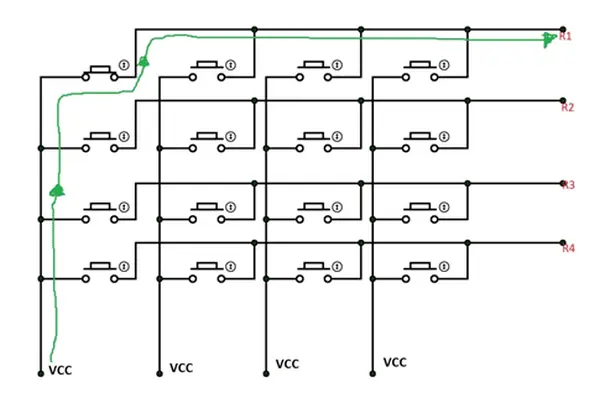
Hence, for the row, R1 is in a high state.
At this moment, we have C1 set to a high state in the first scenario and R1 in a high state in the second scenario, allowing us to determine the matrix position of the button, which corresponds to the number “one.”
If the second button is pressed, C1 will serve as the column, but the high logic obtained in the common column will be ‘R2’. As a result, we will have C1 and R2, enabling us to identify the matrix position of the second button
This is the approach we will employ for programming: we will link the eight keypad pins to eight controller pins. To initiate, we will energize four controller pins to power the four rows of the keypad, while the remaining four pins are designated as inputs. When a button is pressed, the associated column pin will be pulled up, causing the controller pin to rise as well. This will signal the need to swap the input and power roles, thus turning the rows into inputs.
Through this method, we determine the button pressed by the user. This matrix address corresponds to the appropriate number, which is then displayed on the LCD.
Code
#include <avr/io.h>
//header to enable data flow control over pins
#define F_CPU 1000000
//telling controller crystal frequency attached
#include <util/delay.h>
//header to enable delay function in program
#define E 5
//giving name “enable” to 5th pin of PORTD, since it Is connected to LCD enable pin
#define RS 6
//giving name “registerselection” to 6th pin of PORTD, since is connected to LCD RS pin
void send_a_command(unsigned char command);
void send_a_character(unsigned char character);
void send_a_string(char *string_of_characters);
int main(void)
{
DDRB = 0xFF;
//putting portB and portD as output pins
DDRD = 0xFF;
_delay_ms(50);//giving delay of 50ms
int key=0;//allocating integer to reset the LCD once it reaches its display limit
int keypressed=0;//integer for storing matrix value
send_a_command(0x01); //Clear Screen 0x01 = 00000001
_delay_ms(50);
send_a_command(0x38);//telling lcd we are using 8bit command /data mode
_delay_ms(50);
send_a_command(0b00001111);//LCD SCREEN ON and courser blinking
send_a_string("PRESS A KEY");//displaying a string
send_a_command(0x80 + 0x40 +0);// moving courser to second line of LCD
DDRA=0xF0;//taking column pins as input and row pins as output
_delay_ms(1);
PORTA=0x0F;// powering the row ins
_delay_ms(1);
while(1)
{
if (PINA!=0b11110000)//in any of column pins goes high execute the loop
{
_delay_ms(5);
keypressed = PINA;//taking the column value into integer
DDRA ^=0b11111111;//making rows as inputs and columns as ouput
_delay_ms(1);
PORTA ^= 0b11111111;//powering columns
_delay_ms(1);
keypressed |=PINA;taking row value and OR ing it to column value
if (keypressed==0b00010001)
{
send_a_string("1");//if row1 and column1 is high show “1”
key++;
}
if (keypressed==0b00010010)
{
send_a_string("4");// if row1 and column2 is high show “4”
key++;
}
if (keypressed==0b00010100)
{
send_a_string("7");// if row1 and column3 is high show “7”
key++;
}
if (keypressed==0b00011000)
{
send_a_string("*");//if row1 and column4 is high show “*”
key++;
}
if (keypressed==0b00100001)
{
send_a_string("2");// if row2 and column1 is high show “2”
key++;
}
if (keypressed==0b00100010)
{
send_a_string("5");// if row2 and column2 is high show “5”
key++;
}
if (keypressed==0b00100100)
{
send_a_string("8");// if row2 and column3 is high show “8”
key++;
}
if (keypressed==0b00101000)
{
send_a_string("0");// if row2 and column4 is high show “0”
key++;
}
if (keypressed==0b01000001)
{
send_a_string("3");
key++;
}
if (keypressed==0b01000010)
{
send_a_string("6");
key++;
}
if (keypressed==0b01000100)
{
send_a_string("9");
key++;
}
if (keypressed==0b01001000)
{
send_a_string("#");
key++;
}
if (keypressed==0b10000001)
{
send_a_string("A");
key++;
}
if (keypressed==0b10000010)
{
send_a_string("B");
key++;
}
if (keypressed==0b10000100)
{
send_a_string("C");
key++;
}
if (keypressed==0b10001000)
{
send_a_string("D");
key++;
}
keypressed=0;//after showing integer erasing the row column memory
DDRA ^=0b11111111;//shifting input and power port
_delay_ms(1);
PORTA ^= 0b11111111;//powering row pins of keypad
_delay_ms(220);
}
if (key==16)//if 16 characters are shown on LCD
{
send_a_command(0x01);//clear lcd
send_a_string("PRESS A KEY");//display string
send_a_command(0x80 + 0x40 +0);//move courser to second line.
key=0;
}
}
}
void send_a_command(unsigned char command)
{
PORTA = command;
PORTD &= ~ (1<<RS); //putting 0 in RS to tell lcd we are sending command
PORTD |= 1<<E; //telling lcd to receive command /data at the port
_delay_ms(50);
PORTD &= ~1<<E;//telling lcd we completed sending data
PORTA= 0;
}
void send_a_character(unsigned char character)
{
PORTA= character;
PORTD |= 1<<RS;//telling LCD we are sending data not commands
PORTD |= 1<<E;//telling LCD to start receiving command/data
_delay_ms(50);
PORTD &= ~1<<E;//telling lcd we completed sending data/command
PORTA = 0;
}
void send_a_string(char *string_of_characters)
{
while(*string_of_characters > 0)
{
send_a_character(*string_of_characters++);
}
}
- What components are necessary for this project?
The project requires an ATmega32 microcontroller, 5V power supply, AVR-ISP programmer, JHD_162A LCD, capacitors, and eight 10KΩ resistors. - How does the keypad reduce controller pin requirements?
Multiplexing allows connecting 16 buttons using only 8 controller pins instead of the 16 pins that would otherwise be needed. - Which pins connect the LCD data lines to the microcontroller?
The LCD data pins D0 through D7 connect to PORTB pins PB0 through PB7 respectively. - Can I use 4-bit communication mode for the LCD?
Yes, you can opt for 4-bit communication using pins D4-D7, though it makes programming slightly more intricate. - Why are the contrast and READ/WRITE pins connected to ground?
Connecting them to ground sets the LCD to maximum contrast and read mode, simplifying communication by removing the need to manage those pins. - How is the specific button press determined in the software?
The code uses a cross-reference method where rows are powered first to detect columns, then roles are swapped to detect rows and calculate the matrix position. - What happens when 16 characters are displayed on the LCD?
The program clears the screen and displays the prompt PRESS A KEY again after reaching the display limit. - What software tools are required to compile the code?
You need Atmel Studio 6.1 or 6.2 along with ProgISP or Flash Magic for programming.