
Summary of Interfacing Analog Joystick with AVR ATmega32
This article explains how to interface an analog joystick with an AVR microcontroller for precise 2D motion control. The joystick uses two variable resistors to provide voltage outputs corresponding to X and Y axis positions. By reading these voltages via the ADC, the system calculates a range from -512 to +512 to determine direction and speed magnitude for controlling robots or vehicles.
Parts used in the Analog Joystick Interface Project:
- Analog Joystick
- AVR Microcontroller (specifically ATmega32)
- Variable Resistors (two per axis)
- Vcc (5V power supply)
- Ground connection
- ADC channels (Channel 0 and Channel 1)
If you have played games on console you must be knowing what a joystick is. In games a joystick is generally used to control the motion of character or a vehicle (like plane or car). Joystick give a very realistic two dimensional control! Joystick are also used to control the motion of real objects like a robot or a car. Generally we want to control the back and forth motion of any object along with the ability to make it turn left and right. For this we use a common joystick with two axis. The y axis is used to move the object forward and backward, while the x axis is used to turn the object left or right. The type of joystick we are using in this article is an Analog Joystick that means it can give the magnitude of motion along with the direction. For example you can push the joystick little forward to make you robot start moving forward slowly. You can push the joystick further up to increase the speed of forward motion faster. Similarly you can control the speed of robot while making a reverse motion. Turning magnitude can also be controlled in the same way by moving the joystick left or right.
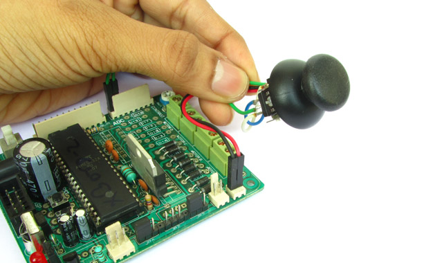
Working of Analog Joystick.
Analog joystick has two variable resistor for two axis. Each variable resistor has three pins, two extreme pins are connected to Vcc(5v in our case) and ground. The center pin is the output pin. The output voltage is between Vcc and GND depending on the position of stick. By measuring the voltage output of two variable resister from which the joystick is built, we can determine the position of stick in x and y axis.
Interface with AVR Micro.
As told above the position of stick can be determined by measuring the voltage from the output of the two variable resistor of the joystick. This can be easily done by using the ADC of AVR Microcontroller. The output of the two variable resistor of the joystick are connected connected with the two channels of ADC. The measurement can be easily done by using our ADC libraries’s ReadADC() function. The return value is between 0-1023, the mid point is 512, so we subtract 512 from the ADC reading. This finally gives us a value between -512 to +511.
      x=ReadADC(0);  //Read ADC Channel 0
      y=ReadADC(1);  //Read ADC Channel 1
      x=x-512;    //512 is the mid point
      y=y-512;


Joystick Wiring.
The joystick is wired as described in the image below. The two extreme points or both the variable resistor are connected to Vcc and Ground respectively. While the central pin provide output, which is connected to ADC input channel.
For more detail: Interfacing Analog Joystick with AVR ATmega32
- How does an analog joystick differ from a standard one?
An analog joystick provides the magnitude of motion along with direction, allowing for variable speed control. - What determines the position of the stick on the x and y axes?
The position is determined by measuring the output voltage of the two variable resistors inside the joystick. - Which function is used to read the ADC values in the code?
The ReadADC() function from the ADC library is used to measure the voltage output. - What is the return value range when using the ReadADC() function?
The return value ranges between 0 and 1023. - How is the final value calculated to get a range from negative to positive?
You subtract 512 from the ADC reading to convert the 0-1023 range into a -512 to +511 range. - Which pins of the variable resistor are connected to Vcc and Ground?
The two extreme pins of each variable resistor are connected to Vcc and Ground respectively. - Where is the central pin of the variable resistor connected?
The central pin provides the output and is connected to the ADC input channel. - Can this setup control both forward/backward motion and turning?
Yes, the Y axis controls forward and backward motion while the X axis controls left and right turning.
